BLIND SPOT MONITORING (BSM) RADAR TEST
id152000003000
Special Service Tool (SST)
|
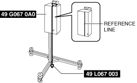
49 L067 003
Plum-bob
|
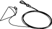 |
49 L067 006
Plum-bob
|
|
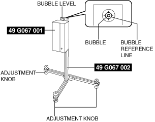
49 G067 001
Doppler simulator
(Component part of 49 G067 0A0)
|
 |
|
49 G067 002
Stand
(Component part of 49 G067 0A0)
|
 |
49 G067 003
AC-DC converter
(Component part of 49 G067 0A0)
|
 |
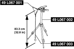
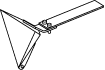
49 L067 001
Reflector
|
 |
|
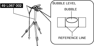
49 L067 002
Tripod
|
 |
-
|
-
|
-
Note
-
• The blind spot monitoring (BSM) radar aiming procedure stores the radar angles in the blind spot monitoring (BSM) control module based on the forced emission of radar at a SST (Doppler simulator or reflector) and performing aiming based on the induced tolerance with the radar as it is currently installed and reflected from the SST (Doppler simulator or reflector).
• The blind spot monitoring (BSM) radar aiming is performed when the blind spot monitoring (BSM) control module, blind spot monitoring (BSM) bracket or the rear bumper is replaced.
• As there are two blind spot monitoring (BSM) control modules, one each on the left and right, radar aiming is performed for each side.
• Radar aiming cannot be performed correctly if obstructions which interfere with radar emission are stuck on the blind spot monitoring (BSM) control modules or the rear bumper. Perform the following procedure before performing the radar aiming.
-
― Verify that there is no water, mud, soiling, sticker adhesion, or repairs done using putty application on the surface of the rear bumper, and that there is no mud, soiling or scratches on the blind spot monitoring (BSM) control modules.
Radar test procedure(doppler simulator)
1. Empty the vehicle by having all occupants leave the vehicle and remove all the cargo except for the spare tire, jack and tools equipped on the vehicle.
2. Adjust the air pressure of each tire to the specified value. (See WHEEL AND TIRE SPECIFICATION.)
3. Park the vehicle on level ground.
-
Caution
-
• If the setting surface height and angle between the vehicle and the SST (reflector) differs, a correct radar test cannot be done. Perform the radar test with the vehicle and SST (reflector) set on level ground.
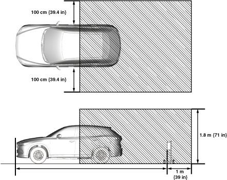
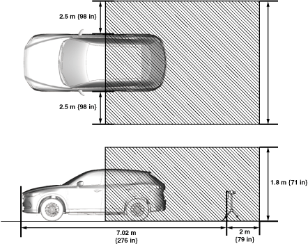
4. Verify that there are no obstructions which interfere with radar emissions such as metal objects in the radar emission area shown in the figure.
-
Caution
-
• If the radar test is performed in the shaded area shown in the figure with obstructions such as covered drain gutters in the floor or other metal reflective objects, it could result in the radar test not being performed correctly. Move all obstructions out of the area, and when performing the radar test, do not have personnel standing in the area.
5. Using the M-MDS, perform a DTC inspection of the BSM control modules and verify that no DTCs are displayed. (See DTC INSPECTION [BLIND SPOT MONITORING (BSM) CONTROL MODULE].)
-
Note
-
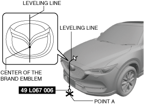
6. Adjust the SST (plum-bob) so that it is aligned with the center of the brand emblem, determine the center position at the front of the vehicle, and mark the center position (point A) on the floor surface.
-
Note
-
• The center of the brand emblem indicates the center position of the vehicle.
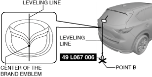
7. Adjust the SST (plum-bob) so that it is aligned with the center of the brand emblem, determine the center position at the rear of the vehicle, and mark the center position (point B) on the floor surface.
-
Note
-
• The center of the brand emblem indicates the center position of the vehicle.
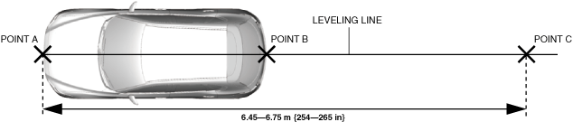
8. Secure the end of the leveling line over point A.
-
Note
-
• Use a commercially-available leveling line.
9. Pull the unsecured end of the leveling line over the vehicle and to the rear and adjust it so that passes over point B.
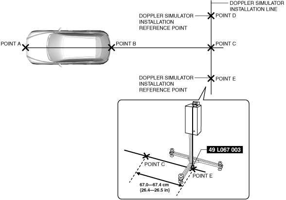
10. Mark the line (position C) within the range of 6.45—6.75 m {254—265 in} from point A and in the direction rearward of the vehicle.
11. Mark the points (points D and E) (SST (Doppler simulator) installation reference points) 67.0—67.4 cm {26.4—26.5 in} from point C on the line which runs perpendicular to the vehicle center line (SST (Doppler simulator) installation reference point).
12. Pull the connected points D, C and E lines (SST (Doppler simulator) installation line).
13. Insert the SST (AC-DC converter) into the side of the SST (Doppler simulator) and turn on the power.
-
Note
-
• Verify that the green lamp on the SST (Doppler simulator) unit illuminates.
14. Loosen the fixing knobs on the side of the SST (Doppler simulator) and adjust the height of the SST (Doppler simulator) so that the height is between 84—86 cm {33.1—33.8 in} from the floor.
-
Caution
-
• If the knobs are loosened excessively, the SST (Doppler simulator) could fall and become damaged. Support the SST (Doppler simulator) with one hand while loosening the fixing knobs.
15. Level the SST (Doppler simulator) by turning the SST (Doppler simulator) adjustment knobs and adjust so that the leveling bubble is centered on the reference line.
16. Drop the SST (plum bob) to the floor along the reference line printed on the SST (Doppler simulator).
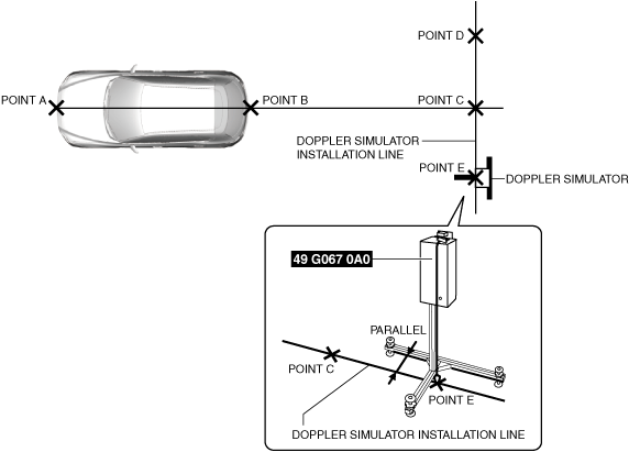
17. Align point D or point E with the end of the SST (plum bomb).
18. Align so that the SST (Doppler simulator) installation line and the SST (Doppler simulator) are level at the center of point D or point E.
19. Remove the SST (plum bob).
20. Perform the radar test using the M-MDS.
21. Connect the M-MDS to DLC-2.
22. After the vehicle is identified, select the following items from the initial screen of the M-MDS.
-
1. "Electrical"
2. "BSM Aiming"
3. "Aiming by using Doppler"
23. Select either the left or right rear BSM control module and perform the radar test according to the instructions on the M-MDS screen.
24. Select either the left or right blind spot monitoring (BSM) control module and perform the radar test according to the instructions on the M-MDS screen.
25. Verify the M-MDS display.
-
• If "Procedure completed successfully" is displayed
-
― The radar aiming procedure is complete
-
• If “This test found error.” Or, "Procedure not completed successfully" is displayed.
-
― Perform an inspection according to the following table.
|
Step
|
Inspection
|
Action
|
|
1
|
DOPPLER SIMULATOR POSITION SET VERIFICATION
• Verify if the Doppler simulator installation position is correct.
• Is the Doppler simulator set in the correct position?
|
Yes
|
Go to the next step.
|
|
No
|
Set the Doppler simulator in the correct position and perform the blind spot monitoring (BSM) radar aiming.
|
|
2
|
INSPECT REAR BUMPER
• Remove the rear bumper.
• Perform the blind spot monitoring (BSM) radar aiming procedure.
• Is "Procedure completed successfully." displayed?
|
Yes
|
Replace the rear bumper and perform the BSM radar aiming procedure.
|
|
No
|
Go to the next step.
|
|
3
|
VERIFY IF BSM CONTROL MODULE OR BSM BRACKET IS MIS-INSTALLED AND IF THERE IS DISTORTION TO VEHICLE INSTALLATION SURFACE
• Verify whether a BSM control module or BSM bracket has been mis-installed, and if there is distortion to the vehicle installation surface.
• Is there poor installation or distortion?
|
Yes
|
Repair or replace the malfunctioning part and perform the BSM radar aiming procedure.
|
|
No
|
Go to the next step.
|
|
4
|
REPEAT REAR MONITORING RADAR AIMING
• Perform the blind spot monitoring (BSM) radar aiming procedure.
• Repeat the M-MDS operation for the blind spot monitoring (BSM) radar aiming 2 or 3 times (Steps 22 to 25).
• Is "Procedure completed correctly." displayed?
|
Yes
|
The blind spot monitoring (BSM) radar aiming is completed.
|
|
No
|
Replace the applicable blind spot monitoring (BSM) control module.
|
Radar test procedure(reflector)
1. Empty the vehicle by having all occupants leave the vehicle and remove all the cargo except for the spare tire, jack and tools.
2. Adjust the air pressure of each tire to the specified value. (See WHEEL AND TIRE SPECIFICATION.)
3. Park the vehicle on level ground.
-
Caution
-
• If the setting surface height and angle between the vehicle and the SST (reflector) differs, correct radar aiming cannot be done. Perform the radar aiming with the vehicle and SST (reflector) set on level ground.
• Verify that there are no obstructions which interfere with radar emissions such as metal objects in the radar emission area shown in the figure.
4. Verify that there are no obstructions which interfere with radar emissions such as metal objects in the radar emission area shown in the figure.
-
Caution
-
• If the radar aiming is performed in the shaded area show in the figure with obstructions such as covered drain gutters in the floor or other metal reflective objects, it could result in the radar aiming not being performed correctly. Move all obstructions out of the area, and when performing the radar aiming, do not have personnel standing in the area.
5. Perform the DTC inspection for the blind spot monitoring (BSM) control module using the M-MDS and verify that no DTCs are displayed. (See DTC INSPECTION [BLIND SPOT MONITORING (BSM) CONTROL MODULE].)
-
Note
-
6. Adjust the SST (plum-bob) so that it is aligned with the center of the brand emblem, determine the center position at the front of the vehicle, and mark the center position (point A) on the floor surface.
-
Note
-
• The center of the brand emblem indicates the center position of the vehicle.
7. Adjust the SST (plum-bob) so that it is aligned with the center of the brand emblem, determine the center position at the rear of the vehicle, and mark the center position (point B) on the floor surface.
-
Note
-
• The center of the brand emblem indicates the center position of the vehicle.
8. Secure the end of the leveling line over point A.
-
Note
-
• Use a commercially-available leveling line.
9. Pull the unsecured end of the leveling line over the vehicle and to the rear and adjust it so that passes over point B.
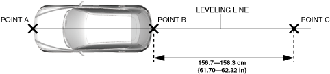
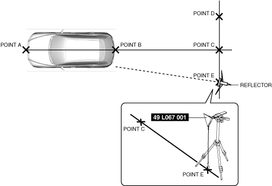
10. Mark the line (position C) within the range of 156.7—158.3 m {61.70—62.32 in} from point A and in the direction rearward of the vehicle.
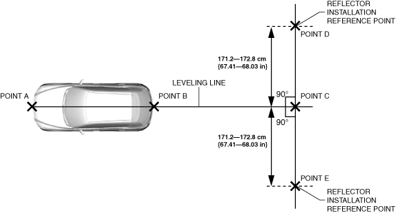
11. Mark the points (points D and E) (SST (reflector) installation reference points) 171.2—172.8 cm {67.41—68.03 in} from point C on the line which runs perpendicular to the vehicle center line (SST (reflector) installation reference point).
12. Pull the connected points D, C and E lines (SST (reflector) installation line).
13. Install the SST (reflector and plum bob) to the SST (tripod).
14. Level the SST (reflector) by adjusting the leveling bubble on the SST (tripod) so that it is centered on the bubble reference line.
15. Adjust so that the height of the SST (reflector) from the floor surface is 83.3 cm {32.8in}.
16. Align so that the SST (Plum-bob) installation line and the SST (Reflector) are level at the center of point D or point E.
17. Adjust the reflecting surface of the SST (reflector) so that it faces the radar emission surface (near a rear bumper corner) of BSM control module.
18. Perform the radar test using the M-MDS.
19. Connect the M-MDS to DLC-2.
20. After the vehicle is identified, select the following items from the initial screen of the M-MDS.
-
1. "Electrical"
2. "BSM Aiming"
3. "Aiming by using Reflector"
21. Select either the left or right blind spot monitoring (BSM) control module and perform the radar test according to the instructions on the M-MDS screen.
22. Verify the M-MDS display.
-
• If "TEST PASSED" is displayed
-
― Radar test is completed
-
• If "TEST FAILED" is displayed
-
― Perform an inspection according to the following table.
|
Step
|
Inspection
|
Action
|
|
1
|
VERIFY REFLECTOR POSITION
• Verify if the reflector installation position is correct.
• Is the reflector set in the correct position?
|
Yes
|
Go to the next step.
|
|
No
|
Set the reflector in the correct position and perform the BSM radar test.
|
|
2
|
INSPECT REAR BUMPER
• Remove the rear bumper.
• Perform the BSM radar test.
• Is "Procedure completed correctly." displayed?
|
Yes
|
Replace the rear bumper and perform the BSM radar test.
|
|
No
|
Go to the next step.
|
|
3
|
VERIFY IF BSM CONTROL MODULE IS MIS-INSTALLED AND IF THERE IS DISTORTION TO VEHICLE INSTALLATION SURFACE
• Verify whether a BSM control module has been mis-installed, and if there is distortion to the vehicle installation surface.
• Is there poor installation or distortion?
|
Yes
|
Repair or replace the malfunctioning part and perform the BSM radar test.
|
|
No
|
Go to the next step.
|
|
4
|
RE-PERFORM THE BSM RADAR TEST
• Perform the BSM radar test.
• Repeat the M-MDS operation for the BSM radar test 2 or 3 times (Steps 22 to 23).
• Is "Procedure completed correctly." displayed?
|
Yes
|
BSM radar test is completed.
|
|
No
|
Replace the BSM control module.
|