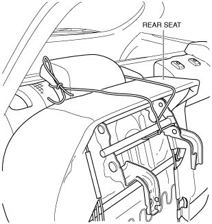
1. Set the rear seat aside as shown in the figure. (See REAR SEAT REMOVAL/INSTALLATION.)
ac5wzw00005750
|
FUEL TANK REMOVAL/INSTALLATION [SKYACTIV-D 2.2]
id0114z7801600
2WD
1. Park the vehicle on a level surface.
2. Perform the “Fuel Line Safety Procedure” referring to the “BEFORE SERVICE PRECAUTION”. (See BEFORE SERVICE PRECAUTION [SKYACTIV-D 2.2].)
3. Drain the fuel. (See FUEL DRAINING PROCEDURE [SKYACTIV-D 2.2].)
4. Perform the following procedure:
ac5wzw00005750
|
5. Partially peel back the floor mat as shown in the figure.
ac5wzw00005751
|
6. Remove the service hole cover.
ac5wzw00005752
|
7. Disconnect the following parts:
8. Remove the floor under cover. (See FLOOR UNDER COVER REMOVAL/INSTALLATION.)
9. Remove the middle pipe. (See EXHAUST SYSTEM REMOVAL/INSTALLATION [SKYACTIV-D 2.2].)
10. Remove in the order shown in the figure.
11. Install in the reverse order of removal.
12. Perform the fuel leakage inspection referring to “AFTER SERVICE PRECAUTION”. (See AFTER SERVICE PRECAUTION [SKYACTIV-D 2.2].)
ac5wzw00005753
|
|
1
|
Joint hose
(See Joint Hose Installation Note.)
|
|
2
|
Fuel tank strap
|
|
3
|
Evaporative hose
|
|
4
|
Breather hose
|
|
5
|
Fuel gauge sender unit
|
|
6
|
Fuel tank
|
Evaporative Hose Removal Note
1. Disconnect the evaporative hose on the fuel-filler pipe side.
2. Remove the following parts as a single unit:
3. Remove the evaporative hose from the fuel tank.
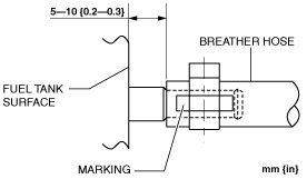
Breather Hose Installation Note
1. Align the marking and install the breather hose as shown in the figure.
Fuel tank side
ac5wzw00005754
|
Fuel-filler pipe side
ac5wzw00005755
|
Joint Hose Installation Note
1. Install the joint hose as shown in the figure.
Fuel tank side
ac5wzw00005756
|
Fuel-filler pipe side
ac5wzw00005757
|
4WD
1. Park the vehicle on a level surface.
2. Perform the “Fuel Line Safety Procedure” referring to the “BEFORE SERVICE PRECAUTION”. (See BEFORE SERVICE PRECAUTION [SKYACTIV-D 2.2].)
3. Drain the fuel. (See FUEL DRAINING PROCEDURE [SKYACTIV-D 2.2].)
4. Perform the following procedure:
Main side
ac5wzw00005750
|
Sub side
ac5wzw00005758
|
5. Partially peel back the floor mat as shown in the figure.
Main side
ac5wzw00005751
|
Sub side
ac5wzw00005759
|
6. Remove the service hole cover.
Main side
ac5wzw00005752
|
Sub side
ac5wzw00005760
|
7. Disconnect the following parts:
8. Remove the floor under cover. (See FLOOR UNDER COVER REMOVAL/INSTALLATION.)
9. Remove the middle pipe. (See EXHAUST SYSTEM REMOVAL/INSTALLATION [SKYACTIV-D 2.2].)
10. Remove the propeller shaft. (See PROPELLER SHAFT REMOVAL/INSTALLATION.)
11. Remove in the order shown in the figure.
12. Install in the reverse order of removal.
13. Perform the fuel leakage inspection referring to “AFTER SERVICE PRECAUTION”. (See AFTER SERVICE PRECAUTION [SKYACTIV-D 2.2].)
ac5wzw00005761
|
|
1
|
Joint hose
(See Joint Hose Installation Note.)
|
|
2
|
Fuel tank strap
|
|
3
|
Evaporative hose
|
|
4
|
Breather hose
|
|
5
|
Fuel gauge sender unit (main)
|
|
6
|
Fuel gauge sender unit (sub)
|
|
7
|
Fuel tank
|
Evaporative Hose Removal Note
1. Disconnect the evaporative hose on the fuel-filler pipe side.
2. Remove the following parts as a single unit:
3. Remove the evaporative hose from the fuel tank.
Breather Hose Installation Note
1. Align the marking and install the breather hose as shown in the figure.
Fuel tank side
ac5wzw00005754
|
Fuel-filler pipe side
ac5wzw00005755
|
Joint Hose Installation Note
1. Install the joint hose as shown in the figure.
Fuel tank side
ac5wzw00005756
|
Fuel-filler pipe side
ac5wzw00005757
|