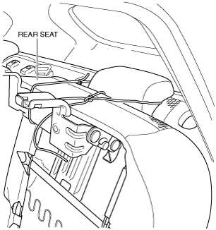
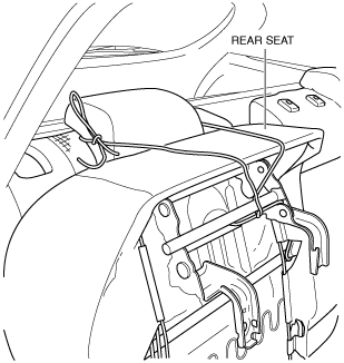
1. Set the rear seat aside as shown in the figure. (See REAR SEAT REMOVAL/INSTALLATION.)
ac5uuw00000392
|
FUEL TANK REMOVAL/INSTALLATION [SKYACTIV-G 2.0, SKYACTIV-G 2.5]
id0114z9801600
2WD
1. Level the vehicle.
2. Complete the “BEFORE SERVICE PRECAUTION”. (See BEFORE SERVICE PRECAUTION [SKYACTIV-G 2.0, SKYACTIV-G 2.5].)
3. Drain the fuel. (See FUEL DRAINING PROCEDURE [SKYACTIV-G 2.0, SKYACTIV-G 2.5].)
4. Using the following procedure:
ac5uuw00000392
|
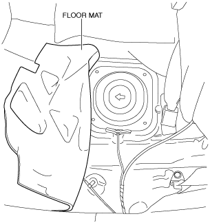
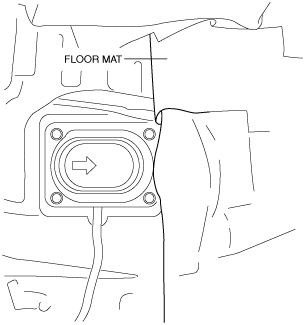
5. Partially peel back the floor mat as shown in the figure.
ac5uuw00000393
|
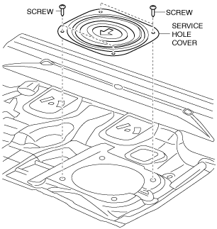
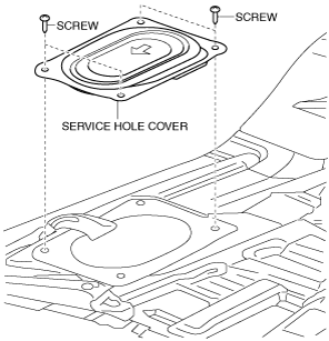
6. Remove the service hole cover.
ac5uuw00000394
|
7. Disconnect the following parts:
8. Remove the floor under cover. (See FLOOR UNDER COVER REMOVAL/INSTALLATION.)
9. Disconnect the HO2S connector.
10. Remove the TWC and HO2S as a single unit. (See EXHAUST SYSTEM REMOVAL/INSTALLATION [SKYACTIV-G 2.0, SKYACTIV-G 2.5].)
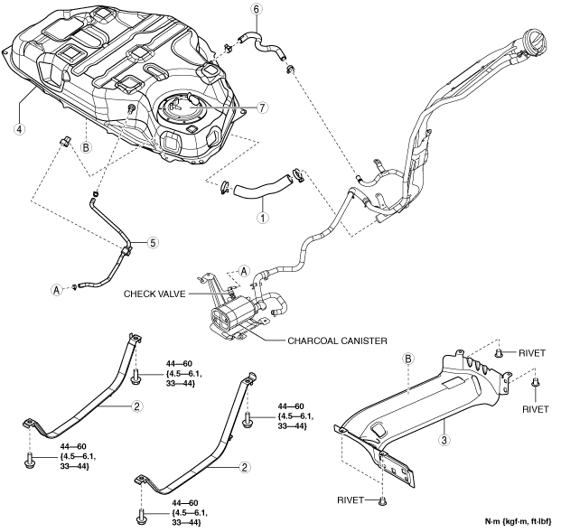
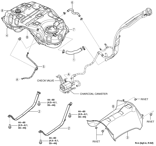
11. Remove in the order indicated in the table.
12. Install in the reverse order of removal.
13. Complete the “AFTER SERVICE PRECAUTION”. (See AFTER SERVICE PRECAUTION [SKYACTIV-G 2.0, SKYACTIV-G 2.5].)
ac5wzw00001388
|
|
1
|
Joint hose
(See Joint hose installation note.)
|
|
2
|
Fuel tank strap
|
|
3
|
Fuel tank insulator
|
|
4
|
Fuel tank
(See Fuel tank removal note.)
|
|
5
|
Evaporative hose
|
|
6
|
Breather hose
|
|
7
|
Fuel pump unit
|
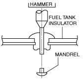
Fuel tank insulator removal note
1. Push out the mandrel using a hammer and punch (2—2.8 mm {0.08—0.11 in} diameter).
ac5wzw00002710
|
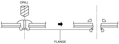
2. Remove the flange using a drill (5 mm {0.20 in} drill bit).
ar8uuw00001479
|
Fuel tank removal note
1. Disconnect the breather hose from the fuel-filler pipe.
2. Disconnect the evaporative hose from the check valve.
3. Remove the following parts as single unit.
4. Remove the fuel tank.
Evaporative hose installation note
1. Install the evaporative hose as shown in the figure.
ac5wzw00006574
|
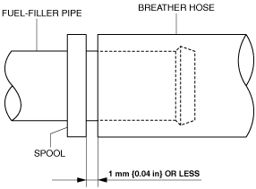
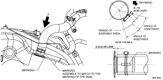
Breather hose installation note
1. Install the breather hose as shown in the figure.
Fuel tank side
ac5wzw00006575
|
Fuel-filler pipe side
ac5wzw00001390
|
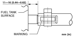
Joint hose installation note
1. Install the joint hose as shown in the figure.
Fuel tank side
ac5uuw00000398
|
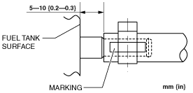
Fuel-filler pipe side
ac5uuw00000399
|
4WD
1. Level the vehicle.
2. Complete the “BEFORE SERVICE PRECAUTION”. (See BEFORE SERVICE PRECAUTION [SKYACTIV-G 2.0, SKYACTIV-G 2.5].)
3. Drain the fuel. (See FUEL DRAINING PROCEDURE [SKYACTIV-G 2.0, SKYACTIV-G 2.5].)
4. Using the following procedure:
Main side
ac5uuw00000392
|
Sub side
ac5uuw00000400
|
5. Partially peel back the floor mat as shown in the figure.
Main side
ac5uuw00000393
|
Sub side
ac5uuw00000401
|
6. Remove the service hole cover.
Main side
ac5uuw00000394
|
Sub side
ac5uuw00000402
|
7. Disconnect the following parts:
8. Remove the floor under cover. (See FLOOR UNDER COVER REMOVAL/INSTALLATION.)
9. Disconnect the HO2S connector.
10. Remove the TWC and HO2S as a single unit. (See EXHAUST SYSTEM REMOVAL/INSTALLATION [SKYACTIV-G 2.0, SKYACTIV-G 2.5].)
11. Remove the propeller shaft. (See PROPELLER SHAFT REMOVAL/INSTALLATION.)
12. Remove in the order indicated in the table.
13. Install in the reverse order of removal.
14. Complete the “AFTER SERVICE PRECAUTION”. (See AFTER SERVICE PRECAUTION [SKYACTIV-G 2.0, SKYACTIV-G 2.5].)
ac5wzw00001391
|
|
1
|
Joint hose
(See Joint hose installation note.)
|
|
2
|
Fuel tank strap
|
|
3
|
Fuel tank insulator
|
|
4
|
Fuel tank
(See Fuel tank removal note.)
|
|
5
|
Evaporative hose
|
|
6
|
Breather hose
|
|
7
|
Fuel pump unit
|
|
8
|
Fuel gauge sender unit (sub)
|
Fuel tank insulator removal note
1. Push out the mandrel using a hammer and punch (2—2.8 mm {0.08—0.11 in} diameter).
ac5wzw00002710
|
2. Remove the flange using a drill (5 mm {0.20 in} drill bit).
ar8uuw00001479
|
Fuel tank removal note
1. Disconnect the breather hose from the fuel-filler pipe.
2. Disconnect the evaporative hose from the check valve.
3. Remove the following parts as single unit.
4. Remove the fuel tank.
Evaporative hose installation note
1. Install the evaporative hose as shown in the figure.
ac5wzw00006574
|
Breather hose installation note
1. Install the breather hose as shown in the figure.
Fuel tank side
ac5wzw00006575
|
Fuel-filler pipe side
ac5wzw00001390
|
Joint hose installation note
1. Install the joint hose as shown in the figure.
Fuel tank side
ac5uuw00000398
|
Fuel-filler pipe side
ac5uuw00000399
|