 |
ac5wzw00007822
EXHAUST GAS TEMPERATURE SENSOR REMOVAL/INSTALLATION [SKYACTIV-D 2.2]
id0140z7446400
Exhaust Gas Temperature Sensor No.1
1. Disconnect the negative battery cable. (See NEGATIVE BATTERY CABLE DISCONNECTION/CONNECTION [SKYACTIV-D 2.2].)
2. Remove the battery. (See BATTERY REMOVAL/INSTALLATION [SKYACTIV-D 2.2].)
3. Remove the air pipe and air hose. (See INTAKE-AIR SYSTEM REMOVAL/INSTALLATION [SKYACTIV-D 2.2].)
4. Disconnect the exhaust gas temperature sensor No.1 connector.
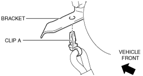
5. Remove the clip A from the bracket.
ac5wzw00007822
|
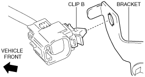
6. Remove the clip B from the bracket.
ac5wzw00007823
|
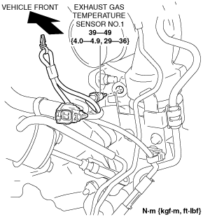
7. Remove the exhaust gas temperature sensor No.1. (See Exhaust gas temperature sensor No.1 installation note.)
ac5wzw00007824
|
ac5wzw00008481
|
8. Install in the reverse order of removal.
Exhaust gas temperature sensor No.1 installation note
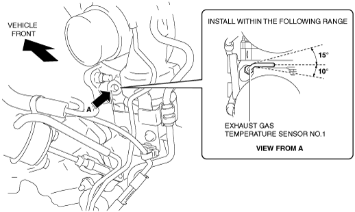
1. Install the exhaust gas temperature sensor No.1 shown in the figure.
ac5wzw00004445
|
Exhaust Gas Temperature Sensor No.2
1. Disconnect the negative battery cable. (See NEGATIVE BATTERY CABLE DISCONNECTION/CONNECTION [SKYACTIV-D 2.2].)
2. Remove the engine cover. (See ENGINE COVER REMOVAL/INSTALLATION [SKYACTIV-D 2.2].)
3. Remove the insulator. (See TIMING CHAIN REMOVAL/INSTALLATION [SKYACTIV-D 2.2].)
4. Disconnect the exhaust gas temperature sensor No.2 connector.
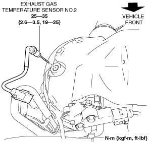
5. Remove the exhaust gas temperature sensor No.2. (See Exhaust gas temperature sensor No.2 installation note.)
ac5wzw00006395
|
6. Install in the reverse order of removal.
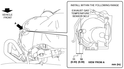
Exhaust gas temperature sensor No.2 installation note
1. Install the exhaust gas temperature sensor No.2 shown in the figure.
ac5wzw00004443
|
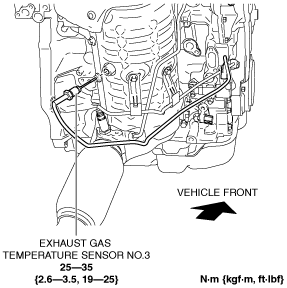
Exhaust Gas Temperature Sensor No.3
ac5wzw00004446
|
1. Disconnect the negative battery cable. (See NEGATIVE BATTERY CABLE DISCONNECTION/CONNECTION [SKYACTIV-D 2.2].)
2. Lift up the vehicle.
3. Remove the following parts:
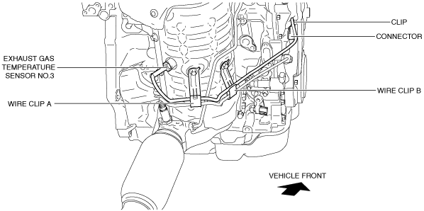
4. Disconnect the exhaust gas temperature sensor No.3 connector.
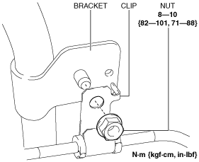
5. Remove the clip from the bracket.
ac5wzw00006396
|
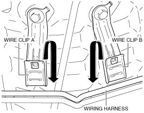
6. Remove the wiring harness from the wire clip A and B. (See Assembly of wiring harness to wire clip note.)
ac5wzw00006397
|
7. Remove the exhaust gas temperature sensor No.3.
ac5wzw00004449
|
8. Install in the reverse order of removal.
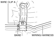
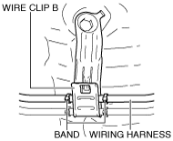
Assembly of wiring harness to wire clip note
ac5wzw00004450
|
ac5wzw00004451
|