ac5wzw00002527
|
MASTER CYLINDER REMOVAL/INSTALLATION
id041100801300
1. For the L.H.D., remove the battery. (See BATTERY REMOVAL/INSTALLATION [SKYACTIV-G 2.0, SKYACTIV-G 2.5].) (See BATTERY REMOVAL/INSTALLATION [SKYACTIV-D 2.2].)
2. For the R.H.D., perform the following procedure:
ac5wzw00002527
|
ac5wzw00002528
|
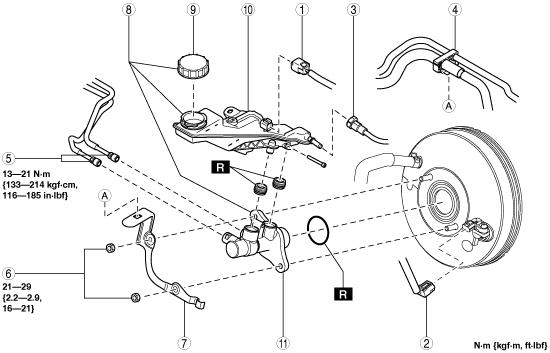
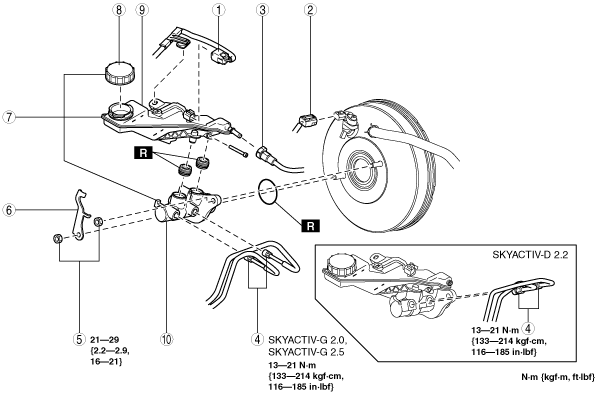
3. Remove in the order indicated in the table.
4. Install in the reverse order of removal.
5. After installation, add brake fluid, bleed the air, and inspect for fluid leakage. (See BRAKE FLUID AIR BLEEDING.)
L.H.D.
ac5wzw00000207
|
|
1
|
Brake fluid level sensor connector
|
|
2
|
Power brake unit vacuum sensor connector (Vehicles with i-stop)
|
|
3
|
Clutch reserve hose (MTX)
|
|
4
|
Hose holder
|
|
5
|
Brake pipe
|
|
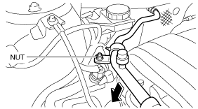
6
|
Nut
|
|
7
|
Bracket
|
|
8
|
Master cylinder
|
|
9
|
Cap
|
|
10
|
Brake fluid reserve tank
|
|
11
|
Cylinder component
|
R.H.D.
ac5wzw00006263
|
|
1
|
Brake fluid level sensor connector
|
|
2
|
Power brake unit vacuum sensor connector (Vehicles with i-stop)
|
|
3
|
Clutch reserve hose (MTX)
|
|
4
|
Brake pipe
|
|
5
|
Nut
|
|
6
|
Bracket
|
|
7
|
Master cylinder
|
|
8
|
Cap
|
|
9
|
Brake fluid reserve tank
|
|
10
|
Cylinder component
|
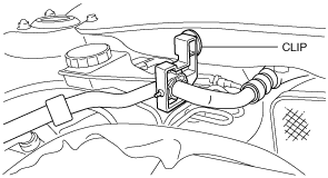
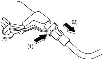
Clutch Reserve Hose Removal Note (MTX)
1. Disconnect the clutch reserve hose in the order shown in the figure.
ac5wzw00002529
|
Clutch Reserve Hose Installation Note (MTX)
1. Insert the clutch reserve hose to the master cylinder.
2. Pull the clutch reserve hose to verify that it does not come off, and reinsert it completely.