|
am3uuw00008598
PURGE SOLENOID VALVE REMOVAL/INSTALLATION [WITHOUT CYLINDER DEACTIVATION (SKYACTIV-G 2.0, SKYACTIV-G 2.5)]
id0116m1804300
1. Disconnect the negative battery terminal. (See NEGATIVE BATTERY TERMINAL DISCONNECTION/CONNECTION.)
2. Remove the plug hole plate. (See PLUG HOLE PLATE REMOVAL/INSTALLATION [WITHOUT CYLINDER DEACTIVATION (SKYACTIV-G 2.0, SKYACTIV-G 2.5)].)
3. Remove the air cleaner and air hose as a single unit. (See INTAKE-AIR SYSTEM REMOVAL/INSTALLATION [WITHOUT CYLINDER DEACTIVATION (SKYACTIV-G 2.0, SKYACTIV-G 2.5)].)
4. Disconnect the high pressure fuel pump connector.
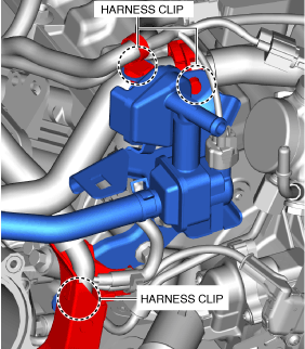
5. Disconnect the harness clip as shown in the figure.
am3uuw00008598
|
6. Disconnect the vacuum hose from the intake manifold. (See INTAKE-AIR SYSTEM REMOVAL/INSTALLATION [WITHOUT CYLINDER DEACTIVATION (SKYACTIV-G 2.0, SKYACTIV-G 2.5)].)
7. Disconnect the harness clip as shown in the figure.
ac5wzw00012240
|
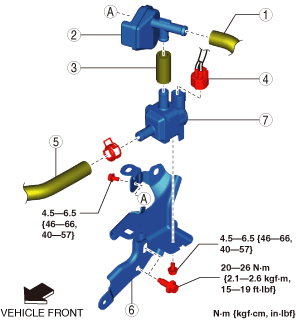
8. Remove in the order indicated in the table.
ac5wzw00013233
|
|
1
|
Evaporative hose No.1
|
|
2
|
Catch tank
|
|
3
|
Evaporative hose No.2
|
|
4
|
Purge solenoid valve connector
|
|
5
|
Evaporative hose No.3
|
|
6
|
Purge solenoid valve bracket
|
|
7
|
Purge solenoid valve
|
9. Install in the reverse order of removal.
Evaporative Hose No.3 Installation Note
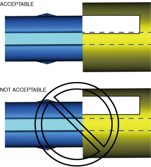
1. Install the evaporative hose No.3 as shown in the figure.
am3uuw00008528
|
Evaporative Hose No.1 Installation Note
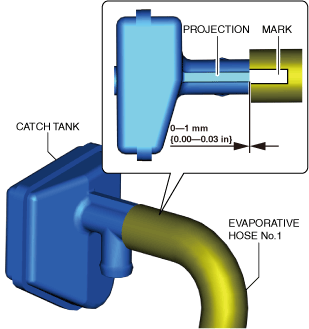
1. Install the evaporative hose No.1 as shown in the figure.
ac5uuw00007799
|
2. Verify that a portion of the mark on evaporative hose No. 1 is covering the catch tank projection area.
ac5uuw00007800
|