 |
ac5wzw00009461
CLUTCH PIPE AND HOSE REMOVAL/INSTALLATION [C66M-R, C66MX-R]
id0510mc157000
1. Disconnect the negative battery terminal. (See NEGATIVE BATTERY TERMINAL DISCONNECTION/CONNECTION.)
2. Remove the front under cover No.2. (See FRONT UNDER COVER No.2 REMOVAL/INSTALLATION.)
3. Remove the plug hole plate. (See PLUG HOLE PLATE REMOVAL/INSTALLATION [WITHOUT CYLINDER DEACTIVATION (SKYACTIV-G 2.0, SKYACTIV-G 2.5)].) (See PLUG HOLE PLATE REMOVAL/INSTALLATION [WITH CYLINDER DEACTIVATION (SKYACTIV-G 2.0, SKYACTIV-G 2.5)].)
4. Remove the following parts as a single unit. (See INTAKE-AIR SYSTEM REMOVAL/INSTALLATION [WITHOUT CYLINDER DEACTIVATION (SKYACTIV-G 2.0, SKYACTIV-G 2.5)].) (See INTAKE-AIR SYSTEM REMOVAL/INSTALLATION [WITH CYLINDER DEACTIVATION (SKYACTIV-G 2.0, SKYACTIV-G 2.5)].)
5. Remove the battery. (See BATTERY REMOVAL/INSTALLATION [WITHOUT CYLINDER DEACTIVATION (SKYACTIV-G 2.0, SKYACTIV-G 2.5)].) (See BATTERY REMOVAL/INSTALLATION [WITH CYLINDER DEACTIVATION (SKYACTIV-G 2.0, SKYACTIV-G 2.5)].)
6. Remove the PCM component. (See PCM REMOVAL/INSTALLATION [WITHOUT CYLINDER DEACTIVATION (SKYACTIV-G 2.0, SKYACTIV-G 2.5)].) (See PCM REMOVAL/INSTALLATION [WITH CYLINDER DEACTIVATION (SKYACTIV-G 2.0, SKYACTIV-G 2.5)].)
7. Remove the battery tray. (See BATTERY REMOVAL/INSTALLATION [WITHOUT CYLINDER DEACTIVATION (SKYACTIV-G 2.0, SKYACTIV-G 2.5)].) (See BATTERY REMOVAL/INSTALLATION [WITH CYLINDER DEACTIVATION (SKYACTIV-G 2.0, SKYACTIV-G 2.5)].)
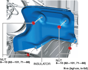
8. Remove the insulator. (R.H.D.)
ac5wzw00009461
|
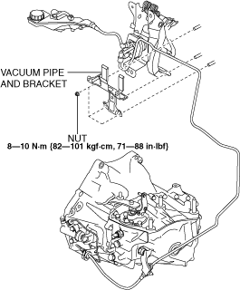
9. Disconnect the vacuum pipe and bracket. (R.H.D.)
ac5wzw00014435
|
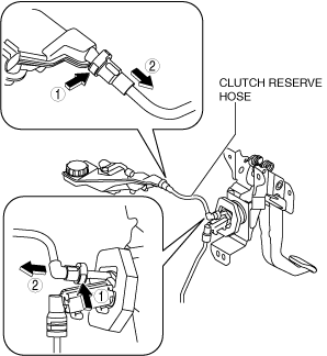
10. Remove the clutch reserve hose and clutch pipes and hose using the following procedure. (See Clutch Reserve Hose And Clutch Pipes And Hose Installation Note.)
ac5uuw00004539
|
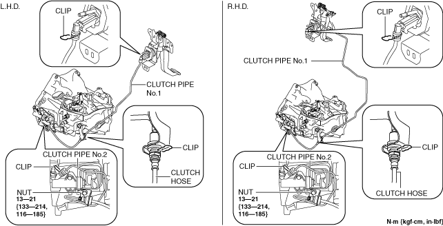
ac5wzw00014436
|
11. Install in the reverse order of removal.
12. Bleed the air from the clutch system. (See CLUTCH FLUID REPLACEMENT/AIR BLEEDING [C66M-R, C66MX-R].)
Clutch Reserve Hose And Clutch Pipes And Hose Installation Note
1. Verify that the seal ring is installed to the clutch pipes and hose connector.
am2zzw00010001
|
2. Install the clutch pipes and hose.
3. Insert the clutch reserve hose connector straight.
4. Pull each engagement of the clutch reserve hose and clutch pipes and hose, verify that they are engaged, and then press all of them again.