|
1
|
INSPECT BATTERY VOLTAGE
• Is the battery terminal voltage normal?
|
Yes
|
Make sure that battery terminal connection is okay.
Go to the next step.
|
|
No
|
Charge or replace the battery, then go to Step 7.
|
|
2
|
INSPECT BATTERY GRAVITY
• Is the battery specific gravity as specified?
|
Yes
|
Go to the next step.
|
|
No
|
Replace the battery, then go to Step 7.
|
|
3
|
INSPECT CHARGING SYSTEM
• Are the generator and drive belt tension normal?
|
Yes
|
Go to the next step.
|
|
No
|
Replace the generator and/or drive belt if necessary.
Go to Step 7.
|
|
4
|
INSPECT FUSE CONDITION
• Is the fuse (EPAS 60A) normal?
|
Yes
|
Go to the next step.
|
|
No
|
Replace the fuse, then go to Step 7.
|
|
5
|
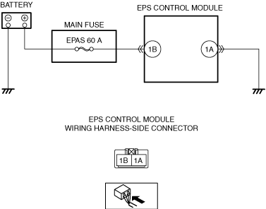
INSPECT EPS CONTROL MODULE POWER SUPPLY CIRCUIT FOR OPEN OR SHORT CIRCUIT
• Start the engine.
• Measure the voltage between following EPS control module terminal (wiring harness-side) and ground.
-
― EPS control module: 1B—ground
• Is the voltage 8 V or more?
|
Yes
|
Go to the next step.
|
|
No
|
Repair or replace the wiring harness (including fuse) between the EPS control module and ground, then go to Step 7.
|
|
6
|
INSPECT EPS CONTROL MODULE GROUND CIRCUIT FOR POOR GROUND OR OPEN CIRCUIT
• Switch the ignition off.
• Inspect for continuity between EPS control module terminal 1A and body ground.
• Is there continuity?
|
Yes
|
Go to the next step.
|
|
No
|
Repair or replace the wiring harness between terminal 1A and body ground, then go to the next step.
|
|
7
|
VERIFY THAT THE SAME DTC IS NOT PRESENT
• Make sure to reconnect all disconnected connectors.
• Using the M-MDS, clear the DTC from the EPS control module.
• Using the M-MDS, perform the EPS control module DTC inspection.
• Is the same Pending DTC present?
|
Yes
|
Replace the steering column, then go to the next step.
|
|
No
|
Go to the next step.
|
|
8
|
VERIFY THAT NO OTHER DTCS ARE PRESENT
• Are any other DTCs output?
|
Yes
|
Go to the applicable DTC inspection.
|
|
No
|
DTC troubleshooting completed.
|