 |
ac5uuw00011330
TELEMATICS COMMUNICATION UNIT REMOVAL/INSTALLATION [TYPE-B]
id0922007084f2
1. Disconnect the negative battery terminal. (See NEGATIVE BATTERY TERMINAL DISCONNECTION/CONNECTION.)
2. Remove the following parts:
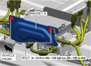
3. Remove the bolts.
ac5uuw00011330
|
4. Remove the bracket A.
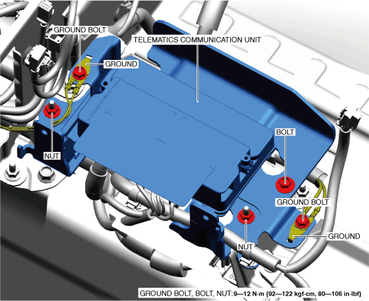
5. Remove the ground bolts.
ac5uuw00011937
|
6. Remove the ground.
7. Remove the bolt.
8. Remove the nuts.
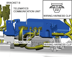
9. Remove the wiring harness clip.
ac5uuw00011327
|
10. Disconnect the connectors.
11. Remove the telematics communication unit and bracket B as a single unit.
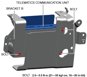
12. Remove the bolts.
ac5uuw00011938
|
13. Remove the telematics communication unit from bracket B.
14. Install in the reverse order of removal.
15. If the telematics communication unit is replaced, perform the procedure after the telematics communication unit replacement. (See Procedure after Telematics Communication Unit Replacement.)
Procedure after Telematics Communication Unit Replacement
Connected Service is not contracted
1. Switch the ignition ON (engine off) to complete global central configuration (GCC) for the telematics communication unit.
2. Clear the DTC. (See CLEARING DTC.)
3. Cancel connected services disable mode. (When transitioning to connected services disable mode) (See SERVICE CAUTIONS FOR VEHICLES WITH TELEMATICS COMMUNICATION SYSTEM.)
4. Cancel connected vehicle maintenance mode. (When transitioning to connected vehicle maintenance mode) (See SERVICE CAUTIONS FOR VEHICLES WITH TELEMATICS COMMUNICATION SYSTEM.)
5. Perform the activating remote control by smart phone. (See ACTIVATING REMOTE CONTROL BY SMART PHONE [TYPE-B].)
6. Perform the telematics communication unit initial setting. (See TELEMATICS COMMUNICATION UNIT INITIAL SETTING [TYPE-B].)
Connected Service is contracted
1. Switch the ignition ON (engine off) to complete global central configuration (GCC) for the telematics communication unit.
2. Clear the DTC. (See CLEARING DTC.)
3. Cancel connected services disable mode. (When transitioning to connected services disable mode) (See SERVICE CAUTIONS FOR VEHICLES WITH TELEMATICS COMMUNICATION SYSTEM.)
4. Cancel connected vehicle maintenance mode. (When transitioning to connected vehicle maintenance mode) (See SERVICE CAUTIONS FOR VEHICLES WITH TELEMATICS COMMUNICATION SYSTEM.)
5. Perform the activating remote control by smart phone. (See ACTIVATING REMOTE CONTROL BY SMART PHONE [TYPE-B].)
6. Perform the telematics communication unit initial setting. (See TELEMATICS COMMUNICATION UNIT INITIAL SETTING [TYPE-B].)
7. Switch the ignition OFF and wait for 5 min or more.
8. Switch the ignition ON (engine off or on) and wait for 1 min or more.
9. Launch the diagnostic assist function. (Refer to the [DIAGNOSTIC ASSIST FUNCTION [CONNECTIVITY MASTER UNIT]] in the workshop manual.)
10. Select [Service Information] on the diagnostic assist function initial screen.
11. Select [TCU Linked Information] on the [Service Information] screen.
12. Verify that the remote service flag in the [Remote Service Flag Information] indicates [1] as shown in the figure.
a30zzw00006781
|
13. Switch the ignition OFF.