 |
am3zzw00032523
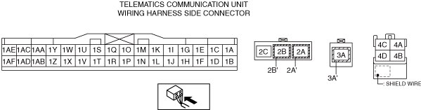
TELEMATICS COMMUNICATION UNIT INSPECTION [TYPE-B]
id0922007777f2
1. Disconnect the negative battery terminal. (See NEGATIVE BATTERY TERMINAL DISCONNECTION/CONNECTION.)
2. Remove the following parts:
3. Connect the negative battery terminal. (See NEGATIVE BATTERY TERMINAL DISCONNECTION/CONNECTION)
4. Measure the voltage at each terminal.
Terminal Voltage Table (Reference)
am3zzw00032523
|
|
Terminal |
Signal name |
Connected to |
Measurement conditions |
Voltage (V) |
Inspection item(s) |
|||
|---|---|---|---|---|---|---|---|---|
|
1A
|
—
|
—
|
—
|
—
|
—
|
|||
|
1B
|
—
|
—
|
—
|
—
|
—
|
|||
|
1C
|
—
|
—
|
—
|
—
|
—
|
|||
|
1D
|
—
|
—
|
—
|
—
|
—
|
|||
|
1E
|
—
|
—
|
—
|
—
|
—
|
|||
|
1F
|
—
|
—
|
—
|
—
|
—
|
|||
|
1G
|
—
|
—
|
—
|
—
|
—
|
|||
|
1H
|
—
|
—
|
—
|
—
|
—
|
|||
|
1I
|
—
|
—
|
—
|
—
|
—
|
|||
|
1J
|
—
|
—
|
—
|
—
|
—
|
|||
|
1K
|
—
|
—
|
—
|
—
|
—
|
|||
|
1L
|
—
|
—
|
—
|
—
|
—
|
|||
|
1M
|
—
|
—
|
—
|
—
|
—
|
|||
|
1N
|
—
|
—
|
—
|
—
|
—
|
|||
|
1O
|
GND1
|
Body ground
|
Under any condition
|
1.0 or less
|
• Body ground
• Related wiring harness
|
|||
|
1P
|
—
|
—
|
—
|
—
|
—
|
|||
|
1Q
|
CAN_H
|
CAN system related module
|
Because this terminal is for communication, determination using terminal voltage inspection is not possible.
|
|||||
|
1R
|
GND3
|
Body ground
|
Under any condition
|
1.0 or less
|
• Body ground
• Related wiring harness
|
|||
|
1S
|
CAN_L
|
CAN system related module
|
Because this terminal is for communication, determination using terminal voltage inspection is not possible.
|
|||||
|
1T
|
GND4
|
Body ground
|
Under any condition
|
1.0 or less
|
• Body ground
• Related wiring harness
|
|||
|
1U
|
GND2
|
Body ground
|
Under any condition
|
1.0 or less
|
• Body ground
• Related wiring harness
|
|||
|
1V
|
—
|
—
|
—
|
—
|
—
|
|||
|
1W
|
—
|
—
|
—
|
—
|
—
|
|||
|
1X
|
—
|
—
|
—
|
—
|
—
|
|||
|
1Y
|
—
|
—
|
—
|
—
|
—
|
|||
|
1Z
|
—
|
—
|
—
|
—
|
—
|
|||
|
1AA
|
—
|
—
|
—
|
—
|
—
|
|||
|
1AB
|
—
|
—
|
—
|
—
|
—
|
|||
|
1AC
|
—
|
—
|
—
|
—
|
—
|
|||
|
1AD
|
—
|
—
|
—
|
—
|
—
|
|||
|
1AE
|
IG1
|
SRS1 7.5 A fuse
|
Switch the ignition ON (engine on or off)
|
B+
|
• SRS1 7.5 A fuse
• Related wiring harness
|
|||
|
Switch the ignition OFF
|
1.0 or less
|
|||||||
|
1AF
|
+B
|
INTERIOR1 15 A fuse
|
Under any condition
|
B+
|
• INTERIOR1 15 A fuse
• Battery
• Related wiring harness
|
|||
|
2A
|
TEL_SIG1
|
TEL antenna No.1
|
Because this terminal is for communication, determination using terminal voltage inspection is not possible.
|
|||||
|
2B
|
GNSS_SIG1
|
TEL antenna No.1
|
Because this terminal is for communication, determination using terminal voltage inspection is not possible.
|
|||||
|
3A
|
TEL_SIG2
|
TEL antenna No.2
|
Because this terminal is for communication, determination using terminal voltage inspection is not possible.
|
|||||
|
4A
|
USB1_GND
|
Connectivity master unit
|
Under any condition
|
1.0 or less
|
• Connectivity master unit
• Related wiring harness
|
|||
|
4B
|
USB1_DATA_P
|
Connectivity master unit
|
Because this terminal is for communication, determination using terminal voltage inspection is not possible.
|
|||||
|
4C
|
USB1_VBUS
|
Connectivity master unit
|
Under any condition
|
Approx. 5.0
|
• Connectivity master unit
• Related wiring harness
|
|||
|
4D
|
USB1_DATA_N
|
Connectivity master unit
|
Because this terminal is for communication, determination using terminal voltage inspection is not possible.
|
|||||