DETERMINING OPEN CIRCUIT LOCATION (CAN-BUS No.2) [TYPE-B (R.H.D.)]
id100271002100
-
Caution
-
• If the malfunctioning part is detected in the communication line, before disconnecting the related connector for inspection, press the connector in the connection direction to verify that there is no looseness or disconnection.
• When disconnecting the connector, verify that there is no damage, deformation, or corrosion of the connector terminals.
1. Verify the CAN system-related module DTCs and the module displayed in red or blue on the M-MDS screen.
2. Apply the communication error DTC and the module displayed in red or blue to the DTC output pattern and malfunctioning location, and select the possible cause for the diagnostic result and the reference for the inspection item. (See DTC Output Pattern And Malfunctioning Location)
-
Note
-
• The open circuit location can be determined by the DTC indicated in the DTC output pattern and malfunctioning location chart. DTCs not listed in the chart are not used for the determination of the open circuit location. (See
DTC Output Pattern And Malfunctioning Location.)
• The module may be displayed in red or blue on the M-MDS screen even if there is no malfunction depending on the vehicle specification.
3. Inspect the possible cause and inspection item of the applicable malfunctioning part.
DTC Output Pattern And Malfunctioning Location
Cross (×): Control error-related DTC
|
M-MDS display
|
DTC
|
DTC output pattern and malfunctioning location
|
|
DTC output module
|
|
Instrument cluster
|
U0142:00
|
|
×
|
|
|
×
|
|
×
|
×
|
|
U0159:00
|
|
×
|
|
×
|
|
|
|
×
|
|
U0232:00
|
|
×
|
|
|
×
|
×
|
|
×
|
|
Climate control unit
|
U0155:00
|
×
|
|
|
|
|
|
|
|
|
Parking assist unit (ultrasonic)
|
U0155:00
|
×
|
|
|
|
|
|
|
|
|
Blind spot monitoring (BSM) control module (LH)
|
U0155:00
|
×
|
|
|
|
|
|
|
|
|
Rear body control module (RBCM)
|
U0155:00
|
×
|
|
|
|
|
|
|
|
|
Gateway unit (GWU)
|
U0151:00
|
|
|
|
|
|
|
|
|
|
U0336:82
|
|
|
|
|
|
|
|
|
|
U2132:00
|
|
|
|
|
|
|
|
|
|
M-MDS display module
|
Module displayed in red or blue
|
|
Instrument cluster
|
×
|
|
|
|
|
|
|
×
|
|
Climate control unit
|
|
×
|
×
|
|
|
|
|
×
|
|
Parking assist unit (ultrasonic)
|
|
×
|
|
×
|
|
|
|
×
|
|
Blind spot monitoring (BSM) control module (LH)
|
|
×
|
|
|
×
|
×
|
|
×
|
|
Rear body control module (RBCM)
|
|
×
|
|
|
×
|
|
×
|
×
|
|
Gateway unit (GWU)
|
|
|
|
|
|
|
|
×
|
|
Diagnostic result
|
|
Possible cause and inspection item
|
|
|
|
|
|
|
|
|
A
Possible cause
-
• Connector terminal disconnection, poor contact, damage, deformation, corrosion
• Instrument cluster power supply voltage or body ground malfunction
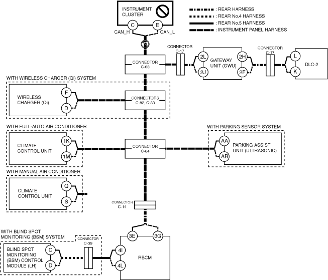
• Open circuit in wiring harness between instrument cluster and connector C-63
• Connector C-63 malfunction
• Instrument cluster malfunction
System wiring diagram
Inspection item
-
• Instrument cluster power supply voltage-related wiring harness and fuse
• Instrument cluster body ground related wiring harness
• Instrument cluster connector
• Connector C-63
• Wiring harness between instrument cluster terminal C and connector C-63
• Wiring harness between instrument cluster terminal E and connector C-63
• Instrument cluster
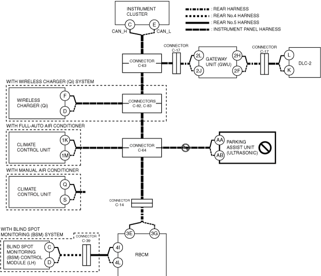
B
With wireless charger (Qi)
-
Possible cause
-
• Connector terminal disconnection, poor contact, damage, deformation, corrosion
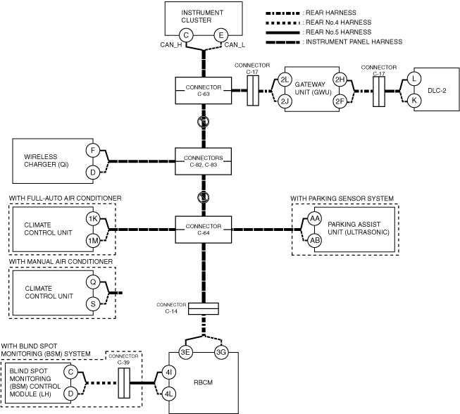
• Open circuit in wiring harness between connector C-63 and connectors C-82, C-83
• Open circuit in wiring harness between connectors C-82, C-83 and connector C-64
• Connector C-63 malfunction
• Connectors C-82, C-83 malfunction
• Connector C-64 malfunction
-
System wiring diagram
-
-
Inspection item
-
• Connector C-63
• Connectors C-82, C-83 malfunction
• Connector C-64
• Wiring harness between connector C-63 and connectors C-82, C-83
• Wiring harness between connectors C-82, C-83 and connector C-64
Without wireless charger (Qi)
-
Possible cause
-
• Connector terminal disconnection, poor contact, damage, deformation, corrosion
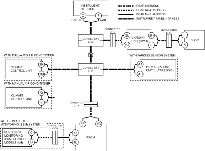
• Open circuit in wiring harness between connector C-63 and connector C-64
• Connector C-63 malfunction
• Connector C-64 malfunction
-
System wiring diagram
-
-
Inspection item
-
• Connector C-63
• Connector C-64
• Wiring harness between connector C-63 and connector C-64
C
Possible cause
-
• Connector terminal disconnection, poor contact, damage, deformation, corrosion
• Climate control unit power supply voltage or body ground malfunction
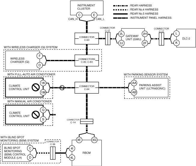
• Open circuit in wiring harness between climate control unit and connector C-64
• Connector C-64 malfunction
• Climate control unit malfunction
System wiring diagram
Inspection item
-
• Climate control unit power supply voltage-related wiring harness and fuse
• Climate control unit body ground related wiring harness
• Climate control unit connector
• Connector C-64
• Wiring harness between climate control unit 1K and connector C-64 (with full-auto air conditioner)
• Wiring harness between climate control unit 1M and connector C-64 (with full-auto air conditioner)
• Wiring harness between climate control unit Q and connector C-64 (with manual air conditioner)
• Wiring harness between climate control unit S and connector C-64 (with manual air conditioner)
• Climate control unit
D
Possible cause
-
• Connector terminal disconnection, poor contact, damage, deformation, corrosion
• Parking assist unit (ultrasonic) power supply voltage or body ground malfunction
• Open circuit in wiring harness between parking assist unit (ultrasonic) and connector C-64
• Connector C-64 malfunction
• Parking assist unit (ultrasonic) malfunction
System wiring diagram
Inspection item
-
• Parking assist (ultrasonic) unit power supply voltage-related wiring harness and fuse
• Parking assist (ultrasonic) unit body ground related wiring harness
• Parking assist (ultrasonic) unit connector
• Connector C-64
• Wiring harness between parking assist unit (ultrasonic) terminal AA and connector C-64
• Wiring harness between parking assist unit (ultrasonic) terminal AB and connector C-64
• Parking assist unit (ultrasonic)
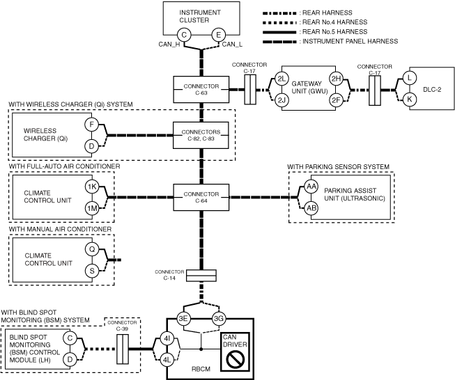
E
Possible cause
-
• Connector terminal disconnection, poor contact, damage, deformation, corrosion
• Connector C-64 malfunction
• Connector C-14 malfunction
• Open circuit in wiring harness between connector C-64 and connector C-14
• Open circuit in wiring harness between connector C-14 and rear body control module (RBCM)
• CAN circuit in rear body control module (RBCM) malfunction
System wiring diagram
Inspection item
-
• Rear body control module (RBCM) connector
• Connector C-64
• Connector C-14
• Wiring harness between connector C-64 and connector C-14
• Wiring harness between connector C-14 and rear body control module (RBCM) terminal 3E
• Wiring harness between connector C-14 and rear body control module (RBCM) terminal 3G
• Rear body control module (RBCM)
-
― Between rear body control module (RBCM) terminal 3E and rear body control module (RBCM) terminal 4I
― Between rear body control module (RBCM) terminal 3G and rear body control module (RBCM) terminal 4L
F
Possible cause
-
• Connector terminal disconnection, poor contact, damage, deformation, corrosion
• Blind spot monitoring (BSM) control module (LH) power supply voltage or body ground malfunction
• Open circuit in wiring harness between blind spot monitoring (BSM) control module (LH) and connector C-39
• Open circuit in wiring harness between connector C-39 and rear body control module (RBCM)
• Connector C-39 malfunction
• Blind spot monitoring (BSM) control module (LH) malfunction
• CAN circuit in rear body control module (RBCM) malfunction
System wiring diagram
Inspection item
-
• Blind spot monitoring (BSM) control module (LH) power supply voltage-related wiring harness and fuse
• Blind spot monitoring (BSM) control module (LH) body ground related wiring harness
• Blind spot monitoring (BSM) control module (LH) connector
• Rear body control module (RBCM) connector
• Connector C-39
• Wiring harness between blind spot monitoring (BSM) control module (LH) terminal C and connector C-39
• Wiring harness between blind spot monitoring (BSM) control module (LH) terminal D and connector C-39
• Wiring harness between connector C-39 and rear body control module (RBCM) terminal 4I
• Wiring harness between connector C-39 and rear body control module (RBCM) terminal 4L
• Rear body control module (RBCM)
-
― Between rear body control module (RBCM) terminal 3E and rear body control module (RBCM) terminal 4I
― Between rear body control module (RBCM) terminal 3G and rear body control module (RBCM) terminal 4L
G
Possible cause
-
• Connector terminal disconnection, poor contact, damage, deformation, corrosion
• Rear body control module (RBCM) power supply voltage or body ground malfunction
• Rear body control module (RBCM) malfunction
System wiring diagram
Inspection item
-
• Rear body control module (RBCM) power supply voltage-related wiring harness and fuse
• Rear body control module (RBCM) body ground related wiring harness
• Rear body control module (RBCM)
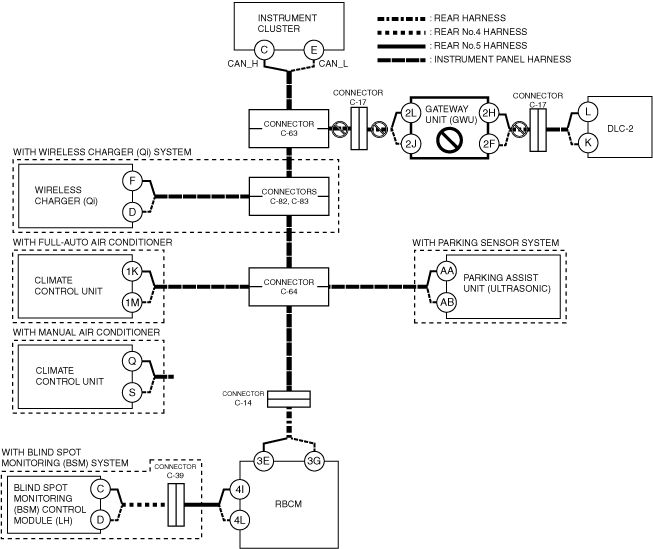
H
Possible cause
-
• Connector terminal disconnection, poor contact, damage, deformation, corrosion
• Gateway unit (GWU) power supply voltage or body ground malfunction
• Open circuit in wiring harness between connector C-63 and connector C-17
• Open circuit in wiring harness between connector C-17 and gateway unit (GWU)
• Connector C-63 malfunction
• Connector C-17 malfunction
• Gateway unit (GWU) malfunction
System wiring diagram
Inspection item
-
• Gateway unit (GWU) power supply voltage-related wiring harness and fuse
• Gateway unit (GWU) body ground related wiring harness
• Gateway unit (GWU) connector
• Connector C-63
• Connector C-17
• Wiring harness between connector C-63 and connector C-17
• Wiring harness between gateway unit (GWU) control module (LH) terminal 2L and connector C-17
• Wiring harness between gateway unit (GWU) control module (LH) terminal 2J and connector C-17
• Wiring harness between gateway unit (GWU) control module (LH) terminal 2H and connector C-17
• Wiring harness between gateway unit (GWU) control module (LH) terminal 2F and connector C-17
• Gateway unit (GWU)