CONTROLLER AREA NETWORK (CAN) MALFUNCTION DIAGNOSIS FLOW [TYPE-B (R.H.D.)]


id100271000100

Note
•  It is necessary to select the CAN BUS to be diagnosed.Verify the module displayed in red (communication disabled) or blue (communication disabled or module not installed) from the network view on the M-MDS, and select any one CAN BUS between No.1 to 4.
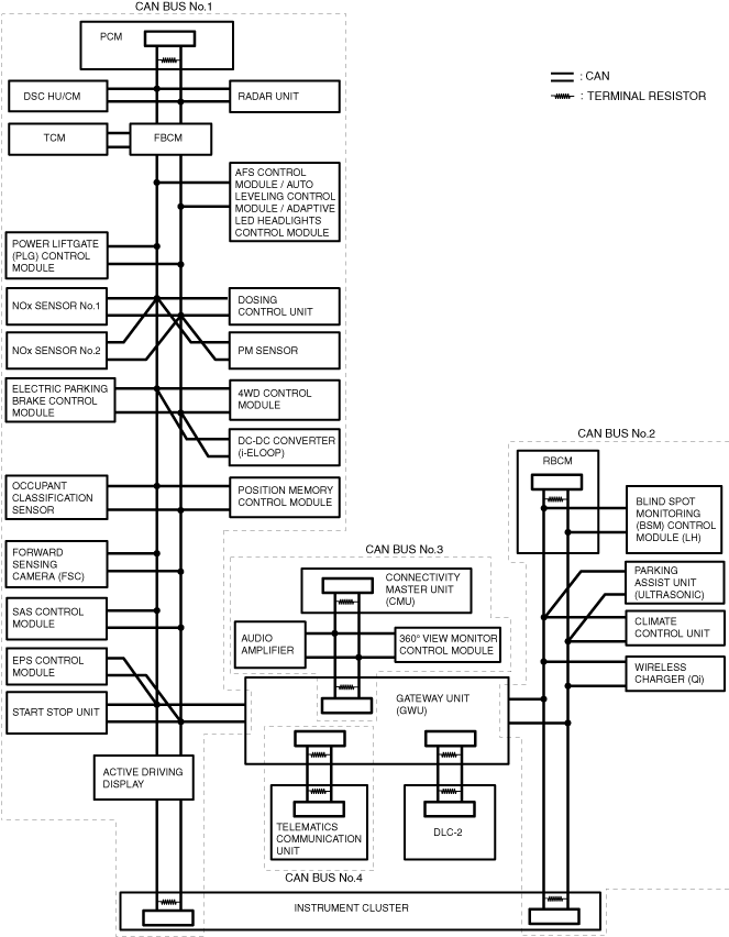
CAN topology

ac5wzw00014758

1.  Connect the M-MDS to the DLC-2.

2.  Verify the module displayed in red or blue on the M-MDS using the network view.

3.  Verify the applicable CAN BUS table and select the CAN BUS reference corresponding to the module displayed in red or blue on the M-MDS. (See CAN BUS table.)

Note
•  The module may be displayed in red or blue on the M-MDS screen even if there is no malfunction depending on the vehicle specification.


CAN BUS table

Cross (×): module displayed in red or blue

CAN communication related module

CAN BUS No.1

CAN BUS No.2

CAN BUS No.3

CAN BUS No.4

PCM
×
     
DSC HU/CM
×
     
Radar unit
×
     
TCM
×
     
Front body control module (FBCM)
×
     
Adaptive front lighting system (AFS) control module / auto leveling control module / adaptive LED headlights control module
×
     
Power liftgate (PLG) control module
×
     
NOx sensor No.1
×
     
NOx sensor No.2
×
     
PM sensor
×
     
Dosing control unit
×
     
Electric parking brake control module
×
     
4WD control module
×
     
DC-DC converter (i-ELOOP)
×
     
Occupant classification sensor
×
     
Position memory control module
×
     
Forward sensing camera (FSC)
×
     
SAS control module
×
     
EPS control module
×
     
Start stop unit
×
     
Active driving display
×
     
Instrument cluster
×
×
   
Wireless charger (Qi)
 
×
   
Climate control unit
 
×
   
Parking assist unit (ultrasonic)
 
×
   
Blind spot monitoring (BSM) control module (LH)
 
×
   
Rear body control module (RBCM)
 
×
   
Audio amplifier
 
 
×
 
360° view monitor control module
 
 
×
 
Connectivity master unit (CMU)
 
 
×
 
Telematics communication unit


×
Gateway unit (GWU)
×
×
×
×
Diagnostic result
CAN BUS reference


CAN-BUS No.1

Caution
•  When disconnecting the connector, verify that there is no looseness, damage, deformation, corrosion, or poor connection of the connector terminals.
•  When inspecting the connector, touch it with a paper clip or similar thin pin without directly inserting a tester probe into the terminal.
•  Disconnect the negative battery terminal before performing any work that requires handling of connectors.

Step

Inspection

Action

1
INSPECT FOR SHORT TO GROUND IN CAN-BUS NO.1
•  Switch the ignition off.
•  Disconnect the negative battery terminal.
•  Inspect for continuity at the following terminals:
―  Between gateway unit (GWU) terminal 3X and body ground
―  Between gateway unit (GWU) terminal 3W and body ground
•  Is there continuity?
Yes
Short to ground in CAN-BUS No.1 has occurred.
Determine the location of a short to ground according to the diagnosis procedure for determining the location of a short to ground in CAN-BUS No.1.
No
Go to the next step.
2
INSPECT FOR SHORT TO POWER SUPPLY IN CAN-BUS No.1
•  Connect the negative battery terminal.
•  Switch the ignition ON (engine off).
•  Measure the voltage at gateway unit (GWU) terminal 3X and 3W.
•  Is the voltage between 1.5—3.5 V?
Yes
Go to the next step.
No
Short to power supply in CAN-BUS No.1 has occurred.
Determine the location of a short to power supply according to the diagnosis procedure for determining the location of a short to power supply in CAN-BUS No.1.
3
INSPECT FOR SHORT BETWEEN CIRCUITS IN CAN-BUS No.1
•  Measure the voltage at gateway unit (GWU) terminals 3X and 3W.
•  Is the voltage at gateway unit (GWU) terminals 3X and 3W the same?
Yes
Short between circuits in CAN-BUS No.1 has occurred.
Determine the location of a short between circuits according to the diagnosis procedure for determining the location of a short between circuits in CAN-BUS No.1.
No
An open circuit in CAN-BUS No.1 has occurred.
Determine the location of an open circuit in CAN-BUS No.1.


CAN-BUS No.2

Caution
•  When disconnecting the connector, verify that there is no looseness, damage, deformation, corrosion, or poor connection of the connector terminals.
•  When inspecting the connector, touch it with a paper clip or similar thin pin without directly inserting a tester probe into the terminal.
•  Disconnect the negative battery terminal before performing any work that requires handling of connectors.

Step

Inspection

Action

1
INSPECT FOR SHORT TO GROUND IN CAN-BUS No.2
•  Switch the ignition off.
•  Disconnect the negative battery terminal.
•  Inspect for continuity at the following terminals:
―  Between gateway unit (GWU) terminal 2L and body ground
―  Between gateway unit (GWU) terminal 2J and body ground
•  Is there continuity?
Yes
Short to ground in CAN-BUS No.2 has occurred.
Determine the location of a short to ground according to the diagnosis procedure for determining the location of a short to ground in CAN-BUS No.2.
No
Go to the next step.
2
INSPECT FOR SHORT TO POWER SUPPLY IN CAN-BUS No.2
•  Connect the negative battery terminal.
•  Switch the ignition ON (engine off).
•  Measure the voltage at gateway unit (GWU) terminal 2L and 2J.
•  Is the voltage between 1.5—3.5 V?
Yes
Go to the next step.
No
Short to power supply in CAN-BUS No.2 has occurred.
Determine the location of a short to power supply according to the diagnosis procedure for determining the location of a short to power supply in CAN-BUS No.2.
3
INSPECT FOR SHORT BETWEEN CIRCUITS IN CAN-BUS No.2
•  Measure the voltage at gateway unit (GWU) terminals 2L and 2J
•  Is the voltage at gateway unit (GWU) terminals 2L and 2J the same?
Yes
Short between circuits in CAN-BUS No.2 has occurred.
Determine the location of a short between circuits according to the diagnosis procedure for determining the location of a short between circuits in CAN-BUS No.2.
No
An open circuit in CAN-BUS No.2 has occurred.
Determine the location of an open circuit in CAN-BUS No.2.


CAN-BUS No.3

Caution
•  When disconnecting the connector, verify that there is no looseness, damage, deformation, corrosion, or poor connection of the connector terminals.
•  When inspecting the connector, touch it with a paper clip or similar thin pin without directly inserting a tester probe into the terminal.
•  Disconnect the negative battery terminal before performing any work that requires handling of connectors.

Step

Inspection

Action

1
INSPECT FOR SHORT TO GROUND IN CAN-BUS No.3
•  Switch the ignition off.
•  Disconnect the negative battery terminal.
•  Inspect for continuity at the following terminals:
―  Between gateway unit (GWU) terminal 4R and body ground
―  Between gateway unit (GWU) terminal 4Q and body ground
•  Is there continuity?
Yes
Short to ground in CAN-BUS No.3 has occurred.
Determine the location of a short to ground according to the diagnosis procedure for determining the location of a short to ground in CAN-BUS No.3.
No
Go to the next step.
2
INSPECT FOR SHORT TO POWER SUPPLY IN CAN-BUS No.3
•  Connect the negative battery terminal.
•  Switch the ignition ON (engine off).
•  Measure the voltage at gateway unit (GWU) terminal 4R and 4Q.
•  Is the voltage between 1.5—3.5 V?
Yes
Go to the next step.
No
Short to power supply in CAN-BUS No.3 has occurred.
Determine the location of a short to power supply according to the diagnosis procedure for determining the location of a short to power supply in CAN-BUS No.3.
3
INSPECT FOR SHORT BETWEEN CIRCUITS IN CAN-BUS No.3
•  Measure the voltage at gateway unit (GWU) terminals 4R and 4Q.
•  Is the voltage at gateway unit (GWU) terminals 4R and 4Q the same?
Yes
Short between circuits in CAN-BUS No.3 has occurred.
Determine the location of a short between circuits according to the diagnosis procedure for determining the location of a short between circuits in CAN-BUS No.3.
No
An open circuit in CAN-BUS No.3 has occurred.
Determine the location of an open circuit in CAN-BUS No.3.


CAN-BUS No.4

Caution
•  When disconnecting the connector, verify that there is no looseness, damage, deformation, corrosion, or poor connection of the connector terminals.
•  When inspecting the connector, touch it with a paper clip or similar thin pin without directly inserting a tester probe into the terminal.
•  Disconnect the negative battery terminal before performing any work that requires handling of connectors.

Step

Inspection

Action

1
INSPECT FOR SHORT TO GROUND IN CAN-BUS No.4
•  Switch the ignition off.
•  Disconnect the negative battery terminal.
•  Inspect for continuity at the following terminals:
―  Between gateway unit (GWU) terminal 3V and body ground
―  Between gateway unit (GWU) terminal 3U and body ground
•  Is there continuity?
Yes
Short to ground in CAN-BUS No.4 has occurred.
Determine the location of a short to ground according to the diagnosis procedure for determining the location of a short to ground in CAN-BUS No.4.
No
Go to the next step.
2
INSPECT FOR SHORT TO POWER SUPPLY IN CAN-BUS No.4
•  Connect the negative battery terminal.
•  Switch the ignition ON (engine off).
•  Measure the voltage at gateway unit (GWU) terminal 3V and 3U.
•  Is the voltage between 1.5—3.5 V?
Yes
Go to the next step.
No
Short to power supply in CAN-BUS No.4 has occurred.
Determine the location of a short to power supply according to the diagnosis procedure for determining the location of a short to power supply in CAN-BUS No.4.
3
INSPECT FOR SHORT BETWEEN CIRCUITS IN CAN-BUS No.4
•  Measure the voltage at gateway unit (GWU) terminals 3V and 3U.
•  Is the voltage at gateway unit (GWU) terminals 3V and 3U the same?
Yes
Short between circuits in CAN-BUS No.4 has occurred.
Determine the location of a short between circuits according to the diagnosis procedure for determining the location of a short between circuits in CAN-BUS No.4.
No
An open circuit in CAN-BUS No.4 has occurred.
Determine the location of an open circuit in CAN-BUS No.4.