|
ac5wzw00014810
DETERMINING OPEN CIRCUIT LOCATION (CAN-BUS No.3) [TYPE-B (R.H.D.)]
id100271002500
1. Verify the CAN system-related module DTCs and the module displayed in red or blue on the M-MDS screen.
2. Apply the communication error DTC and the module displayed in red or blue to the DTC output pattern and malfunctioning location, and select the possible cause for the diagnostic result and the reference for the inspection item. (See DTC Output Pattern And Malfunctioning Location)
3. Inspect the possible cause and inspection item of the applicable malfunctioning part.
4. After repairs, return to CONTROLLER AREA NETWORK (CAN) MALFUNCTION DIAGNOSIS FLOW [TYPE-B (R.H.D.)], and verify that the repairs have been completed. (See CONTROLLER AREA NETWORK (CAN) MALFUNCTION DIAGNOSIS FLOW [TYPE-B (R.H.D.)].)
DTC Output Pattern And Malfunctioning Location
|
M-MDS display |
DTC |
DTC output pattern and malfunctioning location |
|||
|---|---|---|---|---|---|
|
DTC output module |
|||||
|
PCM
|
U0101:00
|
||||
|
U0104:00
|
|||||
|
U010E:00
|
|||||
|
U0121:00
|
|||||
|
U0131:00
|
|||||
|
U0140:00
|
|||||
|
U0151:00
|
|||||
|
U0155:00
|
|||||
|
U0214:00
|
|||||
|
U023A:00
|
|||||
|
U029D:00
|
|||||
|
DSC HU/CM
|
U0100:00
|
||||
|
U0101:00
|
|||||
|
U0104:00
|
|||||
|
U0114:00
|
|||||
|
U0128:00
|
|||||
|
U0131:00
|
|||||
|
U0151:00
|
|||||
|
U0155:00
|
|||||
|
U023A:00
|
|||||
|
Radar unit
|
U0100:00
|
||||
|
U0101:00
|
|||||
|
U0121:00
|
|||||
|
U0131:00
|
|||||
|
U0140:00
|
|||||
|
U0151:00
|
|||||
|
U0155:00
|
|||||
|
U0214:00
|
|||||
|
U023A:00
|
|||||
|
TCM
|
U0100:00
|
||||
|
U0121:00
|
|||||
|
U0131:00
|
|||||
|
U0155:00
|
|||||
|
U0214:00
|
|||||
|
Front body control module (FBCM)
|
U0100:00
|
||||
|
U0101:00
|
|||||
|
U0121:00
|
|||||
|
U0151:00
|
|||||
|
U0155:00
|
|||||
|
U0214:00
|
|||||
|
U023A:00
|
|||||
|
Adaptive front lighting system (AFS) control module
|
U0100:00
|
||||
|
U0131:00
|
|||||
|
U0140:00
|
|||||
|
U0155:00
|
|||||
|
Auto leveling control module
|
U0100:00
|
||||
|
U0140:00
|
|||||
|
U0155:00
|
|||||
|
Adaptive LED headlights control module
|
U0100:00
|
||||
|
U0121:00
|
|||||
|
U0131:00
|
|||||
|
U0140:00
|
|||||
|
U0155:00
|
|||||
|
U0214:00
|
|||||
|
U023A:00
|
|||||
|
Power liftgate (PLG) control module
|
U0100:00
|
||||
|
U0101:00
|
|||||
|
U0155:00
|
|||||
|
U0156:00
|
×
|
×
|
|||
|
U0214:00
|
|||||
|
Dosing control unit
|
U0100:00
|
||||
|
Electric parking brake control module
|
U0100:00
|
||||
|
U0101:00
|
|||||
|
U0121:00
|
|||||
|
U0151:00
|
|||||
|
U0155:00
|
|||||
|
4WD control module
|
U0100:00
|
||||
|
U0101:00
|
|||||
|
U0121:00
|
|||||
|
DC-DC converter (i-ELOOP)
|
U0100:00
|
||||
|
U0151:00
|
|||||
|
U0155:00
|
|||||
|
Position memory control module
|
U0100:00
|
||||
|
U0101:00
|
|||||
|
U0151:00
|
|||||
|
U0155:00
|
|||||
|
U0214:00
|
|||||
|
Forward sensing camera (FSC)
|
U0100:00
|
||||
|
U0104:00
|
|||||
|
U0121:00
|
|||||
|
U0131:00
|
|||||
|
U0140:00
|
|||||
|
U0151:00
|
|||||
|
U0155:00
|
|||||
|
U0156:00
|
×
|
×
|
|||
|
U0182:00
|
|||||
|
U0214:00
|
|||||
|
EPS control module
|
U0100:00
|
||||
|
U0121:00
|
|||||
|
U0126:00
|
|||||
|
U0155:00
|
|||||
|
U0214:00
|
|||||
|
U023A:00
|
|||||
|
Start stop unit
|
U0100:00
|
||||
|
U0101:00
|
|||||
|
U0121:00
|
|||||
|
U0121:87
|
|||||
|
U0131:00
|
|||||
|
U0140:00
|
|||||
|
U0146:00
|
|||||
|
U0151:00
|
|||||
|
U0155:00
|
|||||
|
SAS control module
|
U0100:00
|
||||
|
U0155:00
|
|||||
|
Connectivity master unit (CMU)
|
U0101:00
|
||||
|
U0131:00
|
|||||
|
U0146:00
|
×
|
||||
|
U0151:00
|
|||||
|
U0155:00
|
|||||
|
U0198:02
|
|||||
|
U213C:00
|
|||||
|
U213E:00
|
|||||
|
Active driving display
|
U0100:00
|
||||
|
U0104:00
|
|||||
|
U0155:00
|
|||||
|
U0156:00
|
×
|
×
|
|||
|
U023A:00
|
|||||
|
Instrument cluster
|
U0100:00
|
||||
|
U0101:00
|
|||||
|
U0104:00
|
|||||
|
U0114:00
|
|||||
|
U0121:00
|
|||||
|
U0128:00
|
|||||
|
U0131:00
|
|||||
|
U0140:00
|
|||||
|
U0151:00
|
|||||
|
U0156:00
|
×
|
×
|
|||
|
U0158:00
|
|||||
|
U0182:00
|
|||||
|
U0214:00
|
|||||
|
U0235:00
|
|||||
|
U023A:00
|
|||||
|
Telematics communication unit
|
U0140:00
|
||||
|
U0151:00
|
|||||
|
U0164:00
|
|||||
|
U213C:00
|
|||||
|
Gateway unit (GWU)
|
U0151:00
|
||||
|
U0336:82
|
|||||
|
U2132:00
|
×
|
||||
|
M-MDS display module
|
Module displayed in red or blue
|
||||
|
Connectivity master unit (CMU)
|
×
|
|
|
×
|
|
|
Audio amplifier
|
|
×
|
|
×
|
|
|
360° view monitor control module
|
|
|
×
|
×
|
|
|
Gateway unit (GWU)
|
|
|
|
×
|
|
|
Diagnostic result
|
|||||
|
Possible cause and inspection item
|
|||||
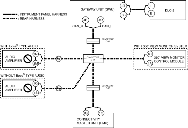
A
Possible cause
System wiring diagram
ac5wzw00014810
|
Inspection item
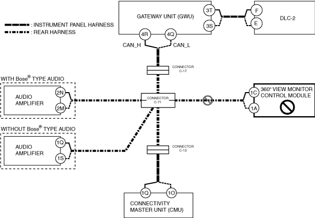
B
Possible cause
System wiring diagram
ac5wzw00014811
|
Inspection item
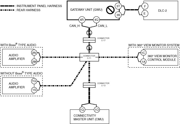
C
Possible cause
System wiring diagram
ac5wzw00014812
|
Inspection item
D
Possible cause
System wiring diagram
ac5wzw00014813
|
Inspection item