 |
ac5wzw00014822
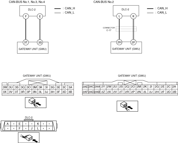
ERROR IS DISPLAYED ON VEHICLE IDENTIFICATION [BETWEEN VEHICLE AND VCM-2] SCREEN [TYPE-B (R.H.D.)]
id100271005300
System Wiring Diagram
ac5wzw00014822
|
Determination Procedure
|
Step |
Inspection |
Action |
|
|---|---|---|---|
|
1
|
INSPECT DLC-2 GROUND CIRCUIT
• Switch the ignition off.
• Disconnect the negative battery terminal.
• Inspect for continuity between DLC-2 terminal J and body ground.
• Is there continuity?
|
Yes
|
Go to the next step.
|
|
No
|
A malfunction has occurred between DLC-2 and body ground.
• Repair or replace the malfunctioning location.
|
||
|
2
|
Measure the voltage at DLC-2.
• Connect the negative battery terminal.
• Switch the ignition ON (engine off).
• Measure the voltage at DLC-2 terminal A.
• Is the voltage B+?
|
Yes
|
Go to the next step.
|
|
No
|
A malfunction has occurred between DLC-2 and battery.
• Inspect the following fuse or wiring harness.
• Repair or replace the malfunctioning location.
|
||
|
3
|
INSPECT CAN LINE BETWEEN DLC-2 AND GATEWAY UNIT (GWU) FOR SHORT TO POWER SUPPLY
• Measure the voltage at DLC-2 terminals F and E. (CAN-BUS No.1, No.3, No.4)
• Measure the voltage at DLC-2 terminals L and K. (CAN-BUS No.2)
• Is the voltage between 1.5—3.5 V?
|
Yes
|
Go to Step 5.
|
|
No
|
Go to the next step.
|
||
|
4
|
INSPECT GATEWAY UNIT (GWU) FOR SHORT TO POWER SUPPLY
• Switch the ignition off.
• Disconnect the negative battery terminal.
• Disconnect the connector 3 which has gateway unit (GWU) terminals 3T and 3S. (CAN-BUS No.1, No.3, No.4)
• Disconnect the connector 2 which has gateway unit (GWU) terminals 2H and 2F. (CAN-BUS No.2)
• Connect the negative battery terminal.
• Switch the ignition ON (engine off).
• Measure the voltage at DLC-2 terminals F and E. (CAN-BUS No.1, No.3, No.4)
• Measure the voltage at DLC-2 terminals L and K. (CAN-BUS No.2)
• Is the voltage between 0 V?
|
Yes
|
Replace the gateway unit (GWU) because there is a short to the power supply in the gateway unit (GWU).
|
|
No
|
Repair or replace the wiring harness between the gateway unit (GWU) and DLC-2 because the wiring harness is shorted to the power supply.
|
||
|
5
|
INSPECT CAN LINE BETWEEN DLC-2 AND GATEWAY UNIT (GWU) FOR SHORT BETWEEN CIRCUITS
• Switch the ignition off.
• Disconnect the negative battery terminal.
• Disconnect the connector 3 which has gateway unit (GWU) terminals 3T and 3S. (CAN-BUS No.1, No.3, No.4)
• Disconnect the connector 2 which has gateway unit (GWU) terminals 2H and 2F. (CAN-BUS No.2)
• Inspect for continuity between DLC-2 terminals F and E. (CAN-BUS No.1, No.3, No.4)
• Inspect for continuity between DLC-2 terminals L and K. (CAN-BUS No.2)
• Is there continuity?
|
Yes
|
Repair or replace the wiring harness between the DLC-2 and gateway unit (GWU) because the wiring harness is shorted between circuits.
|
|
No
|
Go to the next step.
|
||
|
6
|
INSPECT GATEWAY UNIT (GWU) FOR SHORT BETWEEN CIRCUITS
• Connect the connector 3 which has gateway unit (GWU) terminals 3T and 3S. (CAN-BUS No.1, No.3, No.4)
• Connect the connector 2 which has gateway unit (GWU) terminals 2H and 2F. (CAN-BUS No.2)
• Connect the negative battery terminal.
• Switch the ignition ON (engine off).
• Measure the voltage at DLC-2 terminals F and E. (CAN-BUS No.1, No.3, No.4)
• Measure the voltage at DLC-2 terminals L and K. (CAN-BUS No.2)
• Is the voltage at DLC-2 terminals F and E the same? (CAN-BUS No.1, No.3, No.4)
• Is the voltage at DLC-2 terminals L and K the same? (CAN-BUS No.2)
|
Yes
|
Replace the gateway unit (GWU) because there is a short to the power supply in the gateway unit (GWU).
|
|
No
|
Go to the next step.
|
||
|
7
|
INSPECT FOR SHORT TO GROUND BETWEEN DLC-2 AND GATEWAY UNIT (GWU)
• Switch the ignition off.
• Disconnect the negative battery terminal.
• Inspect for continuity at the following terminals:
• Is there continuity?
|
Yes
|
Go to the next step.
|
|
No
|
Go to Step 9.
|
||
|
8
|
INSPECT CAN LINE IN GATEWAY UNIT (GWU) FOR SHORT TO GROUND
• Disconnect the connector 3 which has gateway unit (GWU) terminals 3T and 3S. (CAN-BUS No.1, No.3, No.4)
• Disconnect the connector 2 which has gateway unit (GWU) terminals 2H and 2F. (CAN-BUS No.2)
• Inspect for continuity at the following terminals:
• Is there continuity?
|
Yes
|
Repair or replace the wiring harness between the DLC-2 and gateway unit (GWU) because the wiring harness is shorted to ground.
|
|
No
|
Replace the gateway unit (GWU) because there is a short to the power supply in the gateway unit (GWU).
|
||
|
9
|
VERIFY IF MALFUNCTION CAUSE IS OPEN CIRCUIT IN WIRING HARNESS BETWEEN DLC-2 AND GATEWAY UNIT (GWU)
• Inspect for continuity at the following terminals:
• Is there continuity?
|
Yes
|
Because the circuit between the vehicle and VCM-2 is currently normal, go back to the [TROUBLESHOOTING PROCEDURE].
|
|
No
|
• Any of the following malfunctions may have occurred.
|
||