|
1
|
VERIFY MALFUNCTION SYMPTOM
• Switch the ignition to ACC or ON (engine off or on).
• Launch the on-board diagnostic assist function.
• Select assist code “94”.
• Press the [ENTER] and verify that the sound is output from each speaker.
• Is sound output from each speaker in the order?
|
Yes
|
• System is normal.
• Due to the possibility that sound is not output in some modes, verify the malfunction in the symptom troubleshooting chart and perform the other applicable malfunction diagnosis.
|
|
No
|
• No sound is produced from all speakers
With Mazda ERA-GLONASS
-
― Go to the next step.
Without Mazda ERA-GLONASS
-
― Go to Step 3.
• No sound is produced from some speakers
-
― Go to Step 16.
|
|
2
|
VERIFY Mazda ERA-GLONASS CONTROL MODULE DTCs
• Retrieve the Mazda ERA-GLONASS control module DTCs using the M-MDS. (Refer to the [DTC INSPECTION [MAZDA ERA-GLONASS CONTROL MODULE]] in the workshop manual.)
• Are any DTCs displayed?
|
Yes
|
Repair or replace the malfunctioning part according to the applicable DTC troubleshooting.
(Refer to the [DTC TABLE [MAZDA ERA-GLONASS CONTROL MODULE]] in the workshop manual.)
|
|
No
|
Go to the next step.
|
|
3
|
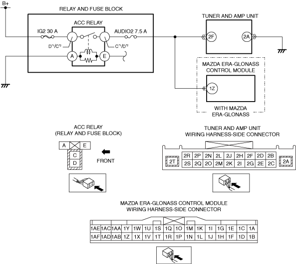
INSPECT TUNER AND AMP UNIT (TAU) CONNECTOR
• Switch the ignition off.
• Disconnect the negative battery terminal. (Refer to the [NEGATIVE BATTERY TERMINAL DISCONNECTION/CONNECTION] in the workshop manual.)
• Disconnect the tuner and amp unit (TAU) connector.
• Inspect the connector engagement and connection condition and inspect the terminals for damage, deformation, corrosion, or disconnection.
• Is the connector normal?
|
Yes
|
Go to the next step.
|
|
No
|
Repair or replace the connector, then go to Step 19.
|
|
4
|
INSPECT AUDIO AMPLIFIER CONNECTOR
• Disconnect the audio amplifier connector.
• Inspect the connector engagement and connection condition and inspect the terminals for damage, deformation, corrosion, or disconnection.
• Is the connector normal?
|
Yes
|
Go to the next step.
|
|
No
|
Repair or replace the connector, then go to Step 19.
|
|
5
|
INSPECT CONNECTIVITY MASTER UNIT (CMU) CONNECTOR
• Disconnect the connectivity master unit (CMU) connector.
• Inspect the connector engagement and connection condition and inspect the terminals for damage, deformation, corrosion, or disconnection.
• Is the connector normal?
|
Yes
|
Go to the next step.
|
|
No
|
Repair or replace the connector, then go to Step 19.
|
|
6
|
INSPECT DC-DC CONVERTER (i-ELOOP) CONNECTOR
• Disconnect the service plug. (Refer to the [SERVICE PLUG DISCONNECTION/CONNECTION] in the workshop manual.)
• Disconnect the DC-DC converter (i-ELOOP) connector.
• Inspect the connector engagement and connection condition and inspect the terminals for damage, deformation, corrosion, or disconnection.
• Is the connector normal?
|
Yes
|
Go to the next step.
|
|
No
|
Repair or replace the connector, then go to Step 19.
|
|
7
|
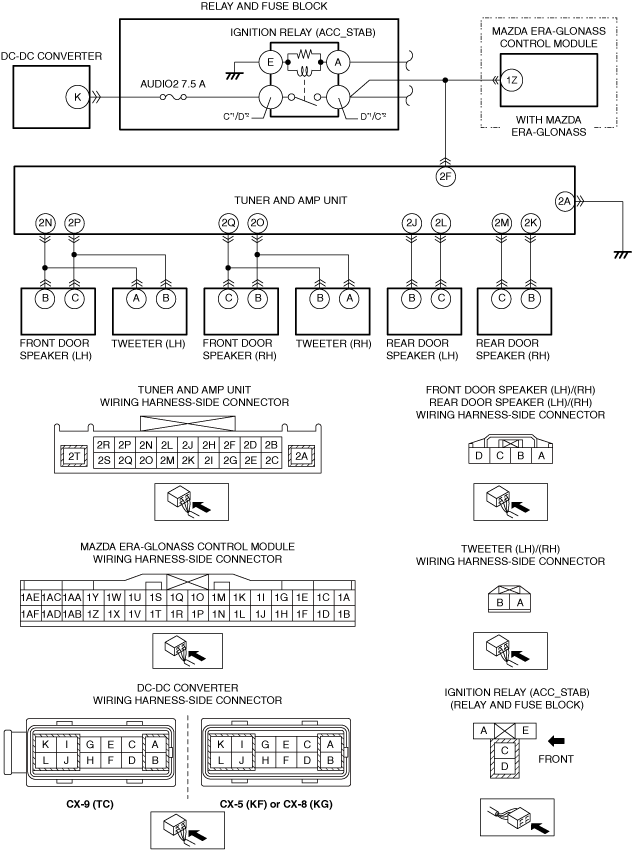
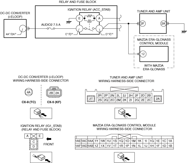
INSPECT IGNITION RELAY (ACC_STAB) RELAY
• Remove the ignition relay (ACC_STAB). (Refer to the [RELAY LOCATION] in the workshop manual.)
• Inspect the ignition relay (ACC_STAB). (Refer to the [RELAY INSPECTION] in the workshop manual.)
• Is the ignition relay (ACC_STAB) normal?
|
Yes
|
Replace the ignition relay (ACC_STAB), then go to Step 19.
(Refer to the [RELAY LOCATION] in the workshop manual.)
|
|
No
|
Go to the next step.
|
|
8
|
INSPECT TUNER AND AMP UNIT (TAU) ACC POWER SUPPLY VOLTAGE
• Verify that the tuner and amp unit (TAU) connector is disconnected.
• Reconnect the negative battery terminal. (Refer to the [NEGATIVE BATTERY TERMINAL DISCONNECTION/CONNECTION] in the workshop manual.)
• Switch the ignition to ACC or ON (engine off or on).
• Measure the voltage at the following terminals (wiring harness-side):
-
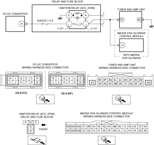
― Ignition relay (ACC_STAB) terminal C (CX-9 (TC))
― Ignition relay (ACC_STAB) terminal D (CX-5 (KF))
• Is the voltage B+?
|
Yes
|
Go to the next step.
|
|
No
|
Inspect the AUDIO2 7.5 A fuse.
• If the fuse is blown:
-
― AUDIO2 7.5 A fuse—Ignition relay (ACC_STAB) terminal C (CX-9 (TC))
― AUDIO2 7.5 A fuse—Ignition relay (ACC_STAB) terminal D (CX-5 (KF))
If there is a common connector:
-
• Inspect the common connector and terminals for corrosion, damage, or disconnection and the common wiring harnesses for short to ground to determine the malfunctioning location.
• Repair or replace the malfunctioning location.
If there is no common connector:
-
• Repair or replace the wiring harness which is shorted to ground.
• Replace the fuse.
• If the fuse is damaged:
-
― Replace the fuse.
• If the fuse is normal:
-
― Refer to the wiring diagram and verify whether or not there is a common connector between the following terminals:
-
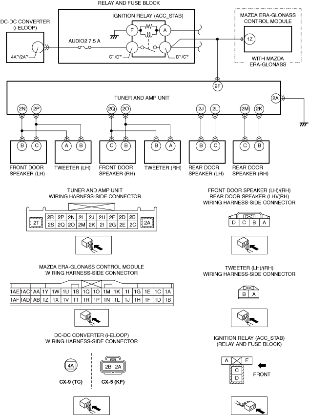
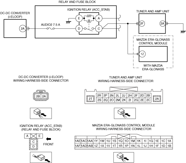
• DC converter (i-ELOOP) terminal 4A—Ignition relay (ACC_STAB) terminal C (CX-9 (TC))
• DC converter (i-ELOOP) terminal 2A—Ignition relay (ACC_STAB) terminal D (CX-5 (KF))
If there is a common connector:
-
• Inspect the common connector and terminals for corrosion, damage, or disconnection and the common wiring harnesses for an open circuit to determine the malfunctioning location.
• Repair or replace the malfunctioning location.
If there is no common connector:
-
• Repair or replace the wiring harness which has an open circuit.
Go to Step 19.
|
|
9
|
VERIFY IF MALFUNCTION CAUSE IS OPEN CIRCUIT IN WIRING HARNESS BETWEEN TUNER AND AMP UNIT (TAU) AND BODY GROUND
• Switch the ignition off.
• Disconnect the negative battery terminal. (Refer to the [NEGATIVE BATTERY TERMINAL DISCONNECTION/CONNECTION] in the workshop manual.)
• Verify that the tuner and amp unit (TAU) connector is disconnected.
• Inspect the wiring harness for continuity between tuner and amp unit (TAU) terminal 2A (wiring harness side) and body ground.
• Is there continuity?
|
Yes
|
Go to the next step.
|
|
No
|
Refer to the wiring diagram and verify if there is a common connector between the tuner and amp unit (TAU) terminal 2A and body ground.
If there is a common connector:
• Inspect the common connector and terminals for corrosion, damage, or disconnection and the common wiring harnesses for an open circuit to determine the malfunctioning location.
• Repair or replace the malfunctioning location.
If there is no common connector:
• Repair or replace the wiring harness which has an open circuit.
Go to Step 19.
|
|
10
|
VERIFY IF MALFUNCTION CAUSE IS OPEN CIRCUIT IN WIRING HARNESS BETWEEN AUDIO AMPLIFIER AND BODY GROUND
• Verify that the audio amplifier connectors are disconnected.
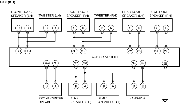
• Inspect the wiring harness for continuity between audio amplifier terminal 3B (wiring harness side) and body ground.
• Is there continuity?
|
Yes
|
Go to the next step.
|
|
No
|
Refer to the wiring diagram and verify if there is a common connector between audio amplifier terminal 3B and body ground.
If there is a common connector:
• Inspect the common connector and terminals for corrosion, damage, or disconnection and the common wiring harnesses for an open circuit to determine the malfunctioning location.
• Repair or replace the malfunctioning location.
If there is no common connector:
• Repair or replace the wiring harness which has an open circuit.
Go to Step 19.
|
|
11
|
INSPECT WIRING HARNESS BETWEEN IGNITION RELAY (ACC_STAB) AND TUNER AND AMP UNIT (TAU) FOR SHORT TO GROUND
• Verify that the ignition relay (ACC_STAB) is removed.
• Verify that the tuner and amp unit (TAU) connector is disconnected.
• Inspect for continuity between ignition relay (ACC_STAB) terminal D*1/C*2 (wiring harness-side) and body ground.
• Is there continuity?
|
Yes
|
Refer to the wiring diagram and verify if there is a common connector between ignition relay (ACC_STAB) terminal D*1/C*2 and tuner and amp unit (TAU) terminal 2F.
If there is a common connector:
• Inspect the common connector and terminals for corrosion, damage, or disconnection and the common wiring harnesses for short to ground to determine the malfunctioning location.
• Repair or replace the malfunctioning location.
Repair or replace the malfunctioning location.
• Repair or replace the wiring harness which has a short to ground.
Go to Step 19.
|
|
No
|
Go to the next step.
|
|
12
|
INSPECT WIRING HARNESS BETWEEN IGNITION RELAY (ACC_STAB) AND TUNER AND AMP UNIT (TAU) FOR OPEN CIRCUIT
• Verify that the ignition relay (ACC_STAB) is removed.
• Verify that the tuner and amp unit (TAU) connector is disconnected.
• Inspect for continuity between ignition relay (ACC_STAB) terminal D*1/C*2 (wiring harness side) and tuner and amp unit (TAU) terminal 2F (wiring harness side).
• Is there continuity?
|
Yes
|
Go to the next step.
|
|
No
|
Refer to the wiring diagram and verify if there is a common connector between ignition relay (ACC_STAB) terminal D*1/C*2 and tuner and amp unit (TAU) terminal 2F.
If there is a common connector:
• Inspect the common connector and terminals for corrosion, damage, or disconnection and the common wiring harnesses for an open circuit to determine the malfunctioning location.
• Repair or replace the malfunctioning location.
Repair or replace the malfunctioning location.
• Repair or replace the wiring harness which has an open circuit.
Go to Step 19.
|
|
13
|
INSPECT DC-DC CONVERTER (i-ELOOP)
• Inspect DC-DC converter (i-ELOOP). (Refer to the [DC-DC CONVERTER (i-ELOOP) INSPECTION] in the workshop manual.)
• Is the DC-DC converter (i-ELOOP) normal?
|
Yes
|
Go to the next step.
|
|
No
|
Replace the DC-DC converter (i-ELOOP), then go to Step 19.
(Refer to the [DC-DC CONVERTER (i-ELOOP) REMOVAL/INSTALLATION] in the workshop manual.)
|
|
14
|
DETERMINE IF MALFUNCTION CAUSE IS AUDIO AMPLIFIER
• Disconnect the negative battery terminal. (Refer to the [NEGATIVE BATTERY TERMINAL DISCONNECTION/CONNECTION] in the workshop manual.)
• Replace the audio amplifier. (Refer to the [AUDIO AMPLIFIER REMOVAL/INSTALLATION] in the workshop manual.)
• Connect all the connectors.
• Reconnect the negative battery terminal. (Refer to the [NEGATIVE BATTERY TERMINAL DISCONNECTION/CONNECTION] in the workshop manual.)
• Connect the service plug. (Refer to the [SERVICE PLUG DISCONNECTION/CONNECTION] in the workshop manual.)
• Switch the ignition to ACC or ON (engine off or on).
• Launch the on-board diagnostic assist function.
• Select assist code “94”.
• Press the [ENTER] and verify that the sound is output from each speaker.
• Is sound output from each speaker in the order?
|
Yes
|
Go to Step 19.
|
|
No
|
Go to the next step.
|
|
15
|
DETERMINE IF MALFUNCTION CAUSE IS TUNER AND AMP UNIT (TAU)
• Disconnect the negative battery terminal. (Refer to the [NEGATIVE BATTERY TERMINAL DISCONNECTION/CONNECTION] in the workshop manual.)
• Replace the tuner and amp unit (TAU). (Refer to the [TUNER AND AMP UNIT (TAU) REMOVAL/INSTALLATION [TYPE-A]] in the workshop manual.)
• Connect all the connectors.
• Reconnect the negative battery terminal. (Refer to the [NEGATIVE BATTERY TERMINAL DISCONNECTION/CONNECTION] in the workshop manual.)
• Switch the ignition to ACC or ON (engine off or on).
• Launch the on-board diagnostic assist function.
• Select assist code “94”.
• Press the [ENTER] and verify that the sound is output from each speaker.
• Is sound output from each speaker in the order?
|
Yes
|
Go to Step 19.
|
|
No
|
Replace the connectivity master unit (CMU), then go to Step 19.
(Refer to the [CONNECTIVITY MASTER UNIT (CMU) REMOVAL/INSTALLATION] in the workshop manual.)
|
|
16
|
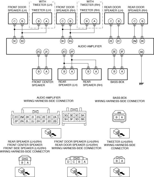
INSPECT SPEAKERS
• Disconnect the negative battery terminal. (Refer to the [NEGATIVE BATTERY TERMINAL DISCONNECTION/CONNECTION] in the workshop manual.)
• Inspect the malfunctioning speaker. (Refer to the [FRONT DOOR SPEAKER INSPECTION] in the workshop manual.)
(Refer to the [TWEETER INSPECTION] in the workshop manual.)
(Refer to the [REAR DOOR SPEAKER INSPECTION] in the workshop manual.)
(Refer to the [BASS-BOX SPEAKER INSPECTION] in the workshop manual.)
(Refer to the [FRONT CENTER SPEAKER INSPECTION] in the workshop manual.)
(Refer to the [FRONT SIDE SPEAKER INSPECTION] in the workshop manual.)
(Refer to the [REAR SPEAKER INSPECTION] in the workshop manual.)
• Is the speaker resistance normal?
|
Yes
|
Go to the next step.
|
|
No
|
Replace the malfunctioning speaker, then go to Step 19.
(Refer to the [FRONT DOOR SPEAKER REMOVAL/INSTALLATION] in the workshop manual.)
(Refer to the [TWEETER REMOVAL/INSTALLATION] in the workshop manual.)
(Refer to the [REAR DOOR SPEAKER REMOVAL/INSTALLATION] in the workshop manual.)
(Refer to the [BASS-BOX REMOVAL/INSTALLATION] in the workshop manual.)
(Refer to the [FRONT CENTER SPEAKER REMOVAL/INSTALLATION] in the workshop manual.)
(Refer to the [FRONT SIDE SPEAKER REMOVAL/INSTALLATION] in the workshop manual.)
(Refer to the [REAR SPEAKER REMOVAL/INSTALLATION] in the workshop manual.)
|
|
17
|
INSPECT SPEAKER CIRCUIT FOR OPEN CIRCUIT
• Disconnect the connector of the malfunctioning speaker and the audio amplifier connector.
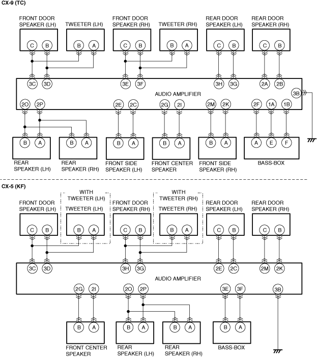
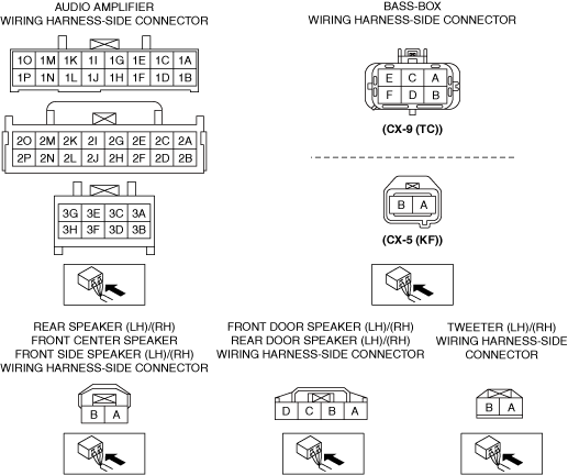
• Verify the continuity of the wiring harness between the following terminals (vehicle wiring harness side) of the speakers which are malfunctioning.
-
― Audio amplifier terminal 3C—Front door speaker (RH) terminal C
― Audio amplifier terminal 3D—Front door speaker (RH) terminal B
― Audio amplifier terminal 3C—Tweeter (RH) terminal B
― Audio amplifier terminal 3D—Tweeter (RH) terminal A
― Audio amplifier terminal 3E—Front door speaker (LH) terminal C (CX-9 (TC))
― Audio amplifier terminal 3F—Front door speaker (LH) terminal B (CX-9 (TC))
― Audio amplifier terminal 3H—Front door speaker (LH) terminal C (CX-5 (KF))
― Audio amplifier terminal 3G—Front door speaker (LH) terminal B (CX-5 (KF))
― Audio amplifier terminal 3E—Tweeter (LH) terminal B (CX-9 (TC))
― Audio amplifier terminal 3F—Tweeter (LH) terminal A (CX-9 (TC))
― Audio amplifier terminal 3H—Tweeter (LH) terminal B (CX-5 (KF))
― Audio amplifier terminal 3G—Tweeter (LH) terminal A (CX-5 (KF))
― Audio amplifier terminal 3H—Rear door speaker (RH) terminal C (CX-9 (TC))
― Audio amplifier terminal 3G—Rear door speaker (RH) terminal B (CX-9 (TC))
― Audio amplifier terminal 2E—Rear door speaker (RH) terminal C (CX-5 (KF))
― Audio amplifier terminal 2C—Rear door speaker (RH) terminal B (CX-5 (KF))
― Audio amplifier terminal 2A—Rear door speaker (LH) terminal C (CX-9 (TC))
― Audio amplifier terminal 2B—Rear door speaker (LH) terminal B (CX-9 (TC))
― Audio amplifier terminal 2M—Rear door speaker (LH) terminal C (CX-5 (KF))
― Audio amplifier terminal 2K—Rear door speaker (LH) terminal B (CX-5 (KF))
― Audio amplifier terminal 2G—Front center speaker terminal B
― Audio amplifier terminal 2I—Front center speaker terminal A
― Audio amplifier terminal 2O—Rear speaker (LH) terminal B
― Audio amplifier terminal 2P—Rear speaker (LH) terminal A
― Audio amplifier terminal 2O—Rear speaker (RH) terminal B
― Audio amplifier terminal 2P—Rear speaker (RH) terminal A
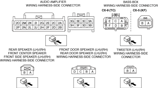
― Audio amplifier terminal 2F—Bass-box terminal A (CX-9 (TC))
― Audio amplifier terminal 1A—Bass-box terminal E (CX-9 (TC))
― Audio amplifier terminal 1B—Bass-box terminal F (CX-9 (TC))
― Audio amplifier terminal 3E—Bass-box terminal B (CX-5 (KF))
― Audio amplifier terminal 3F—Bass-box terminal A (CX-5 (KF))
|
Yes
|
Go to the next step.
|
|
No
|
Refer to the wiring diagram and verify if there is a common connector between the following terminals.
• Audio amplifier terminal 3C—Front door speaker (RH) terminal C
• Audio amplifier terminal 3D—Front door speaker (RH) terminal B
• Audio amplifier terminal 3C—Tweeter (RH) terminal B
• Audio amplifier terminal 3D—Tweeter (RH) terminal A
• Audio amplifier terminal 3E—Front door speaker (LH) terminal C (CX-9 (TC))
• Audio amplifier terminal 3F—Front door speaker (LH) terminal B (CX-9 (TC))
• Audio amplifier terminal 3H—Front door speaker (LH) terminal C (CX-5 (KF))
• Audio amplifier terminal 3G—Front door speaker (LH) terminal B (CX-5 (KF))
• Audio amplifier terminal 3E—Tweeter (LH) terminal B (CX-9 (TC))
• Audio amplifier terminal 3F—Tweeter (LH) terminal A (CX-9 (TC))
• Audio amplifier terminal 3H—Tweeter (LH) terminal B (CX-5 (KF))
• Audio amplifier terminal 3G—Tweeter (LH) terminal A (CX-5 (KF))
• Audio amplifier terminal 3H—Rear door speaker (RH) terminal C (CX-9 (TC))
• Audio amplifier terminal 3G—Rear door speaker (RH) terminal B (CX-9 (TC))
• Audio amplifier terminal 2E—Rear door speaker (RH) terminal C (CX-5 (KF))
• Audio amplifier terminal 2C—Rear door speaker (RH) terminal B (CX-5 (KF))
• Audio amplifier terminal 2A—Rear door speaker (LH) terminal C (CX-9 (TC))
• Audio amplifier terminal 2B—Rear door speaker (LH) terminal B (CX-9 (TC))
• Audio amplifier terminal 2M—Rear door speaker (LH) terminal C (CX-5 (KF))
• Audio amplifier terminal 2K—Rear door speaker (LH) terminal B (CX-5 (KF))
• Audio amplifier terminal 2G—Front center speaker terminal B
• Audio amplifier terminal 2I—Front center speaker terminal A
• Audio amplifier terminal 2O—Rear speaker (LH) terminal B
• Audio amplifier terminal 2P—Rear speaker (LH) terminal A
• Audio amplifier terminal 2O—Rear speaker (RH) terminal B
• Audio amplifier terminal 2P—Rear speaker (RH) terminal A
• Audio amplifier terminal 2F—Bass-box terminal A (CX-9 (TC))
• Audio amplifier terminal 1A—Bass-box terminal E (CX-9 (TC))
• Audio amplifier terminal 1B—Bass-box terminal F (CX-9 (TC))
• Audio amplifier terminal 3E—Bass-box terminal B (CX-5 (KF))
• Audio amplifier terminal 3F—Bass-box terminal A (CX-5 (KF))
|
|
17
|
• Verify the continuity of the wiring harness between the following terminals (vehicle wiring harness side) of the speakers which are malfunctioning.
-
― Audio amplifier terminal 2E—Front side speaker (RH) terminal B (CX-9 (TC))
― Audio amplifier terminal 2C—Front side speaker (RH) terminal A (CX-9 (TC))
― Audio amplifier terminal 2M—Front side speaker (LH) terminal B (CX-9 (TC))
― Audio amplifier terminal 2K—Front side speaker (LH) terminal A (CX-9 (TC))
• Is there continuity?
|
No
|
• Audio amplifier terminal 2E—Front side speaker (RH) terminal B (CX-9 (TC))
• Audio amplifier terminal 2C—Front side speaker (RH) terminal A (CX-9 (TC))
• Audio amplifier terminal 2M—Front side speaker (LH) terminal B (CX-9 (TC))
• Audio amplifier terminal 2K—Front side speaker (LH) terminal A (CX-9 (TC))
If there is a common connector:
• Inspect the common connector and terminals for corrosion, damage, or disconnection and the common wiring harnesses for an open circuit to determine the malfunctioning location.
• Repair or replace the malfunctioning location.
If there is no common connector:
• Repair or replace the wiring harness which has an open circuit.
Go to Step 19.
|
|
18
|
INSPECT SPEAKER CIRCUIT FOR SHORT TO GROUND
• Verify that the connector of the malfunctioning speaker and the audio amplifier connector are disconnected.
• Inspect for continuity between the following terminals (vehicle wiring harness side) of the speakers which are malfunctioning and body ground.
-
― Front door speaker (LH) terminal B
― Front door speaker (LH) terminal C
― Tweeter (LH) terminal B
― Tweeter (LH) terminal A
― Front door speaker (RH) terminal B
― Front door speaker (RH) terminal C
― Tweeter (RH) terminal B
― Tweeter (RH) terminal A
― Rear door speaker (LH) terminal B
― Rear door speaker (LH) terminal C
― Rear door speaker (RH) terminal C
― Rear door speaker (RH) terminal B
― Front center speaker terminal B
― Front center speaker terminal A
― Rear speaker (LH) terminal B
― Rear speaker (LH) terminal A
― Rear speaker (RH) terminal B
― Rear speaker (RH) terminal A
― Bass-box terminal A
― Bass-box terminal E
― Bass-box terminal F
― Front side speaker (RH) terminal B (CX-9 (TC))
― Front side speaker (RH) terminal A (CX-9 (TC))
― Front side speaker (LH) terminal B (CX-9 (TC))
― Front side speaker (LH) terminal A (CX-9 (TC))
|
Yes
|
Refer to the wiring diagram and verify if there is a common connector between the following terminals.
• Audio amplifier terminal 3C—Front door speaker (RH) terminal C
• Audio amplifier terminal 3D—Front door speaker (RH) terminal B
• Audio amplifier terminal 3C—Tweeter (RH) terminal B
• Audio amplifier terminal 3D—Tweeter (RH) terminal A
• Audio amplifier terminal 3E—Front door speaker (LH) terminal C (CX-9 (TC))
• Audio amplifier terminal 3F—Front door speaker (LH) terminal B (CX-9 (TC))
• Audio amplifier terminal 3H—Front door speaker (LH) terminal C (CX-5 (KF))
• Audio amplifier terminal 3G—Front door speaker (LH) terminal B (CX-5 (KF))
• Audio amplifier terminal 3E—Tweeter (LH) terminal B (CX-9 (TC))
• Audio amplifier terminal 3F—Tweeter (LH) terminal A (CX-9 (TC))
• Audio amplifier terminal 3H—Tweeter (LH) terminal B (CX-5 (KF))
• Audio amplifier terminal 3G—Tweeter (LH) terminal A (CX-5 (KF))
• Audio amplifier terminal 3H—Rear door speaker (RH) terminal C (CX-9 (TC))
• Audio amplifier terminal 3G—Rear door speaker (RH) terminal B (CX-9 (TC))
• Audio amplifier terminal 2E—Rear door speaker (RH) terminal C (CX-5 (KF))
• Audio amplifier terminal 2C—Rear door speaker (RH) terminal B (CX-5 (KF))
• Audio amplifier terminal 2A—Rear door speaker (LH) terminal C (CX-9 (TC))
• Audio amplifier terminal 2B—Rear door speaker (LH) terminal B (CX-9 (TC))
• Audio amplifier terminal 2M—Rear door speaker (LH) terminal C (CX-5 (KF))
• Audio amplifier terminal 2K—Rear door speaker (LH) terminal B (CX-5 (KF))
• Audio amplifier terminal 2G—Front center speaker terminal B
• Audio amplifier terminal 2I—Front center speaker terminal A
• Audio amplifier terminal 2O—Rear speaker (LH) terminal B
• Audio amplifier terminal 2P—Rear speaker (LH) terminal A
• Audio amplifier terminal 2O—Rear speaker (RH) terminal B
• Audio amplifier terminal 2P—Rear speaker (RH) terminal A
• Audio amplifier terminal 2F—Bass-box terminal A (CX-9 (TC))
• Audio amplifier terminal 1A—Bass-box terminal E (CX-9 (TC))
• Audio amplifier terminal 1B—Bass-box terminal F (CX-9 (TC))
• Audio amplifier terminal 3E—Bass-box terminal B (CX-5 (KF))
• Audio amplifier terminal 3F—Bass-box terminal A (CX-5 (KF))
|
|
18
|
• Is there continuity?
|
Yes
|
• Audio amplifier terminal 2E—Front side speaker (RH) terminal B (CX-9 (TC))
• Audio amplifier terminal 2C—Front side speaker (RH) terminal A (CX-9 (TC))
• Audio amplifier terminal 2M—Front side speaker (LH) terminal B (CX-9 (TC))
• Audio amplifier terminal 2K—Front side speaker (LH) terminal A (CX-9 (TC))
If there is a common connector:
• Inspect the common connector and terminals for corrosion, damage, or disconnection and the common wiring harnesses for short to ground to determine the malfunctioning location.
• Repair or replace the malfunctioning location.
If there is no common connector:
• Repair or replace the wiring harness which is shorted to ground.
Go to the next step.
|
|
No
|
Go to the next step.
|
|
19
|
VERIFY IF MALFUNCTION CAUSE IS CORRECTED
• Disconnect the negative battery terminal. (Refer to the [NEGATIVE BATTERY TERMINAL DISCONNECTION/CONNECTION] in the workshop manual.)
• Connect all the connectors.
• Reconnect the negative battery terminal. (Refer to the [NEGATIVE BATTERY TERMINAL DISCONNECTION/CONNECTION] in the workshop manual.)
• Connect the service plug. (Refer to the [SERVICE PLUG DISCONNECTION/CONNECTION] in the workshop manual.)
• Switch the ignition to ACC or ON (engine off or on).
• Launch the on-board diagnostic assist function.
• Select assist code “94”.
• Press the [ENTER] and verify that the sound is output from each speaker.
• Is sound output from each speaker in the order?
|
Yes
|
Troubleshooting completed (explain the contents of the servicing to the customer).
|
|
No
|
Verify the malfunction symptom in the symptom troubleshooting chart and perform the other applicable malfunction diagnosis.
|