|
1
|
VERIFY AFTER-MARKET ELECTRICAL COMPONENT INSTALLATION CONDITION
• Verify if a non-genuine, after-market electrical component is installed.
• Has a non-genuine, after-market electrical component been installed?
|
Yes
|
Go to the next step.
|
|
No
|
Go to Step 3.
|
|
2
|
VERIFY IF MALFUNCTION CAUSE IS AFTER-MARKET ELECTRICAL COMPONENT INSTALLATION
• Disconnect the non-genuine, after-market electrical component connectors.
• Verify if the malfunction symptom recurs as stated by the customer.
• Does the malfunction recur?
|
Yes
|
Go to the next step.
|
|
No
|
Explain to the customer that the malfunction occurred due to the after-market electrical component installation.
|
|
3
|
INSPECT REAR MOUNT CAMERA CONDITION
• Is the rear mount camera lens soiled by dust or dirt?
|
Yes
|
Clean the rear mount camera lens, then go to Step 10.
|
|
No
|
Go to the next step.
|
|
4
|
VERIFY IF MALFUNCTION CAUSE IS REAR MOUNT CAMERA
• Are there any scratches or damage on the rear mount camera lens?
|
Yes
|
Replace the rear mount camera lens, then go to Step 10.
(Refer to the [REAR MOUNT CAMERA REMOVAL/INSTALLATION] in the workshop manual.)
|
|
No
|
Go to the next step.
|
|
5
|
INSPECT REAR MOUNT CAMERA CONNECTOR
• Switch the ignition off.
• Disconnect the negative battery terminal. (Refer to the [NEGATIVE BATTERY TERMINAL DISCONNECTION/CONNECTION] in the workshop manual.)
• Disconnect the rear mount camera connector.
• Inspect the connector engagement and connection condition and inspect the terminals for damage, deformation, corrosion, or disconnection.
• Is the connector normal?
|
Yes
|
Go to the next step.
|
|
No
|
Repair or replace the connector, then go to Step 10.
|
|
6
|
INSPECT CONNECTIVITY MASTER UNIT (CMU) CONNECTOR
• Disconnect the connectivity master unit (CMU) connector.
• Inspect the connector engagement and connection condition and inspect the terminals for damage, deformation, corrosion, or disconnection.
• Is the connector normal?
|
Yes
|
Go to the next step.
|
|
No
|
Repair or replace the connector, then go to Step 10.
|
|
7
|
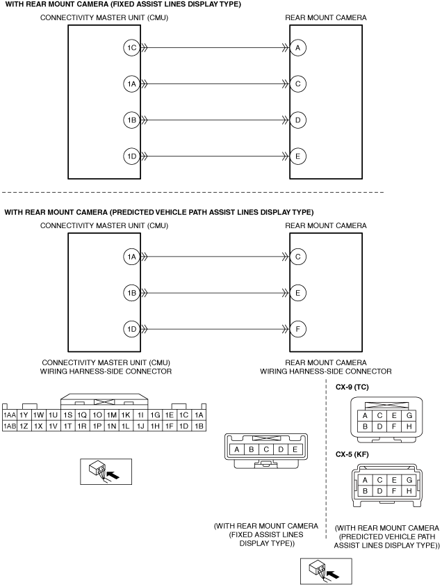
VERIFY IF MALFUNCTION CAUSE IS OPEN CIRCUIT IN WIRING HARNESS BETWEEN CONNECTIVITY MASTER UNIT (CMU) AND REAR MOUNT CAMERA
• Verify that the rear mount camera and connectivity master unit (CMU) connectors are disconnected.
• Inspect the wiring harness for continuity between the following terminals (vehicle wiring harness side).
With rear mount camera (fixed assist lines display type)
-
― Connectivity master unit (CMU) terminal 1B—Rear mount camera terminal D
― Connectivity master unit (CMU) terminal 1C—Rear mount camera terminal A
― Connectivity master unit (CMU) terminal 1D—Rear mount camera terminal E
With rear mount camera (predicted vehicle path assist lines display type)
-
― Connectivity master unit (CMU) terminal 1B—Rear mount camera terminal E
― Connectivity master unit (CMU) terminal 1D—Rear mount camera terminal F
• Is there continuity?
|
Yes
|
Go to the next step.
|
|
No
|
Refer to the wiring diagram and verify if there is a common connector between the following terminals.
With rear mount camera (fixed assist lines display type)
• Connectivity master unit (CMU) terminal 1B—Rear mount camera terminal D
• Connectivity master unit (CMU) terminal 1C—Rear mount camera terminal A
• Connectivity master unit (CMU) terminal 1D—Rear mount camera terminal E
With rear mount camera (predicted vehicle path assist lines display type)
• Connectivity master unit (CMU) terminal 1B—Rear mount camera terminal E
• Connectivity master unit (CMU) terminal 1D—Rear mount camera terminal F
If there is a common connector:
• Inspect the common connector and terminals for corrosion, damage, or disconnection and the common wiring harnesses for an open circuit to determine the malfunctioning location.
• Repair or replace the malfunctioning location.
If there is no common connector:
• Repair or replace the wiring harness which has an open circuit.
Go to Step 10.
|
|
8
|
VERIFY IF MALFUNCTION CAUSE IS SHORT CIRCUIT TO POWER SUPPLY IN WIRING HARNESS BETWEEN CONNECTIVITY MASTER UNIT (CMU) AND REAR MOUNT CAMERA
• Verify that the rear mount camera and connectivity master unit (CMU) connectors are disconnected.
• Reconnect the negative battery terminal. (Refer to the [NEGATIVE BATTERY TERMINAL DISCONNECTION/CONNECTION] in the workshop manual.)
• Switch the ignition to ACC or ON (engine off or on).
• Measure the voltage at the following terminals (vehicle wiring harness side).
With rear mount camera (fixed assist lines display type)
-
― Rear mount camera terminal D
― Rear mount camera terminal A
― Rear mount camera terminal E
With rear mount camera (predicted vehicle path assist lines display type)
-
― Rear mount camera terminal E
― Rear mount camera terminal F
• Is the voltage B+?
|
Yes
|
Refer to the wiring diagram and verify if there is a common connector between the following terminals.
With rear mount camera (fixed assist lines display type)
• Connectivity master unit (CMU) terminal 1B—Rear mount camera terminal D
• Connectivity master unit (CMU) terminal 1C—Rear mount camera terminal A
• Connectivity master unit (CMU) terminal 1D—Rear mount camera terminal E
With rear mount camera (predicted vehicle path assist lines display type)
• Connectivity master unit (CMU) terminal 1B—Rear mount camera terminal E
• Connectivity master unit (CMU) terminal 1D—Rear mount camera terminal F
If there is a common connector:
• Inspect the common connector and terminals for corrosion, damage, or disconnection and the common wiring harnesses for short to power supply to determine the malfunctioning location.
• Repair or replace the malfunctioning location.
If there is no common connector:
• Repair or replace the wiring harness which is shorted to the power supply.
Go to Step 10.
|
|
No
|
Go to the next step.
|
|
9
|
DETERMINE IF MALFUNCTION CAUSE IS REAR MOUNT CAMERA
• Switch the ignition off.
• Disconnect the negative battery terminal. (Refer to the [NEGATIVE BATTERY TERMINAL DISCONNECTION/CONNECTION] in the workshop manual.)
• Replace the rear mount camera. (Refer to the [REAR MOUNT CAMERA REMOVAL/INSTALLATION] in the workshop manual.)
• Connect all the connectors.
• Reconnect the negative battery terminal. (Refer to the [NEGATIVE BATTERY TERMINAL DISCONNECTION/CONNECTION] in the workshop manual.)
• Apply the parking brake.
• Switch the ignition to ACC or ON (engine off or on).
• Selector lever is in R position. (ATX)
• Shift lever is in reverse position. (MTX)
• Is rear mount camera image output normally?
|
Yes
|
Troubleshooting completed (explain the contents of the servicing to the customer).
|
|
No
|
Replace the connectivity master unit (CMU), then go to the next step.
(Refer to the [CONNECTIVITY MASTER UNIT (CMU) REMOVAL/INSTALLATION] in the workshop manual.)
|
|
10
|
VERIFY IF MALFUNCTION CAUSE IS CORRECTED
• Switch the ignition off.
• Disconnect the negative battery terminal. (Refer to the [NEGATIVE BATTERY TERMINAL DISCONNECTION/CONNECTION] in the workshop manual.)
• Connect all the connectors.
• Reconnect the negative battery terminal. (Refer to the [NEGATIVE BATTERY TERMINAL DISCONNECTION/CONNECTION] in the workshop manual.)
• Apply the parking brake.
• Switch the ignition to ACC or ON (engine off or on).
• Selector lever is in R position. (ATX)
• Shift lever is in reverse position. (MTX)
• Is rear mount camera image output normally?
|
Yes
|
Troubleshooting completed (explain the contents of the servicing to the customer).
|
|
No
|
Verify the malfunction symptom in the symptom troubleshooting chart and perform the other applicable malfunction diagnosis.
|