 |
acxaaw00000398
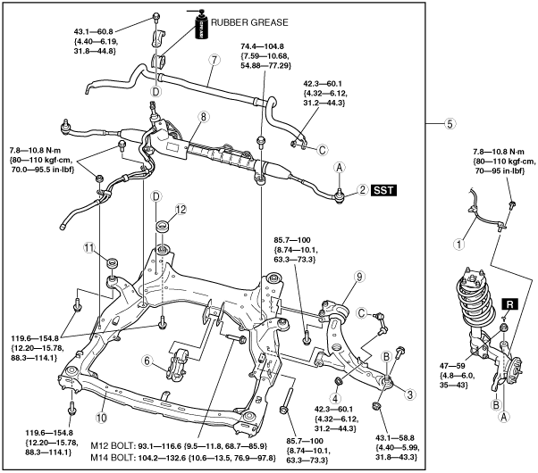
FRONT CROSSMEMBER REMOVAL/INSTALLATION [R.H.D.]
id0213008010b2
1. Remove the side cover and under cover.
2. Drain the power steering fluid. (See POWER STEERING FLUID INSPECTION.)
3. Remove the front auto leveling sensor. (Vehicle with headlight auto leveling system) (See FRONT AUTO LEVELING SENSOR REMOVAL/INSTALLATION.)
4. Remove the transverse member. (See TRANSVERSE MEMBER REMOVAL/INSTALLATION.)
5. Remove the intermediate shaft installation bolt, and disconnect the steering shaft. (See STEERING WHEEL AND COLUMN REMOVAL/INSTALLATION.)
6. Remove in the order indicated in the table.
7. Install in the reverse order of removal.
8. When replace the front crossmember, inspect the front wheel alignment and adjust it if necessary. (See FRONT WHEEL ALIGNMENT.)
acxaaw00000398
|
|
1
|
ABS wheel speed sensor
|
|
2
|
Tie-rod end ball joint
|
|
3
|
Front lower arm ball joint
|
|
4
|
Stabilizer control link lower side nut
|
|
5
|
Steering gear and linkage, front stabilizer, front lower arm and front crossmember component
|
|
6
|
No. 1 engine mount
|
|
7
|
Front stabilizer
|
|
8
|
Steering gear and linkage
|
|
9
|
Front lower arm
|
|
10
|
Front crossmember
|
|
11
|
Front crossmember mounting rubber (front)
|
|
12
|
Front crossmember mounting rubber (rear)
|
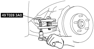
Tie-rod End Ball Joint Removal Note
1. Remove the tie-rod end ball joint locknut.
2. Disconnect the tie-rod end ball joint using the SST.
acxaaw00001609
|
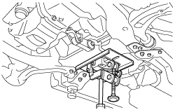
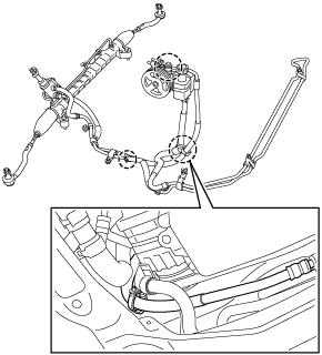
Steering Gear And Linkage, Front Stabilizer, Front Lower Arm And Front Crossmember Component Removal Note
1. Support the crossmember component with a jack.
acxaaw00001610
|
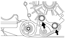
2. Loosen the bolts of the No.1 engine mount (engine side).
acxuuw00001689
|
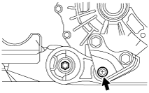
3. Remove the No.1 engine mount bolt (engine side).
acxuuw00001690
|
4. Lower the steering gear and linkage, front stabilizer, front lower arm and front crossmember component slightly.
5. Disconnect the following parts.
acxaaw00001611
|
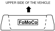
Front Crossmember Mounting Rubber (front) Installation Note
1. Install the front crossmember mounting rubber (front) so that the smaller outer diameter is facing upward.
acxaaw00001612
|
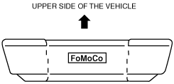
Front Crossmember Mounting Rubber (rear) Installation Note
1. Install the front crossmember mounting rubber (rear) so that the larger outer diameter is facing upward.
acxaaw00001613
|
No. 1 Engine Mount Installation Note
1. Temporarily tighten the No.1 engine mount bolt (crossmember side).
Steering Gear And Linkage, Front Stabilizer, Front Lower Arm And Front Crossmember Component Installation Note
1. Raise the steering gear and linkage, front stabilizer, front lower arm and front crossmember component to the appropriately level, and install the following parts.
acxaaw00001611
|
2. Install the steering gear and linkage, front stabilizer, front lower arm and front crossmember component.
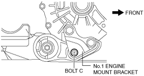
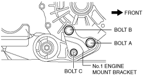
3. Temporarily install the No.1 engine mount bolt C in the figure.
acxaaw00001590
|
4. Tighten the No.1 engine mount bracket bolt A and B in order of A→B.
acxaaw00001592
|
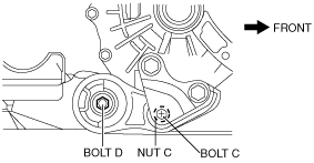
5. Tighten bolt C.
acxaaw00001623
|
6. Tighten the No.1 engine mount bolt D (crossmember side).