 |
acxaaw00000789
AUTOMATIC TRANSAXLE REMOVAL/INSTALLATION [AW6A-EL, AW6AX-EL]
id051723802400
1. Disconnect the negative battery cable.
2. Remove the following parts.
3. Drain the ATF. (See AUTOMATIC TRANSAXLE FLUID (ATF) REPLACEMENT [AW6A-EL, AW6AX-EL].)
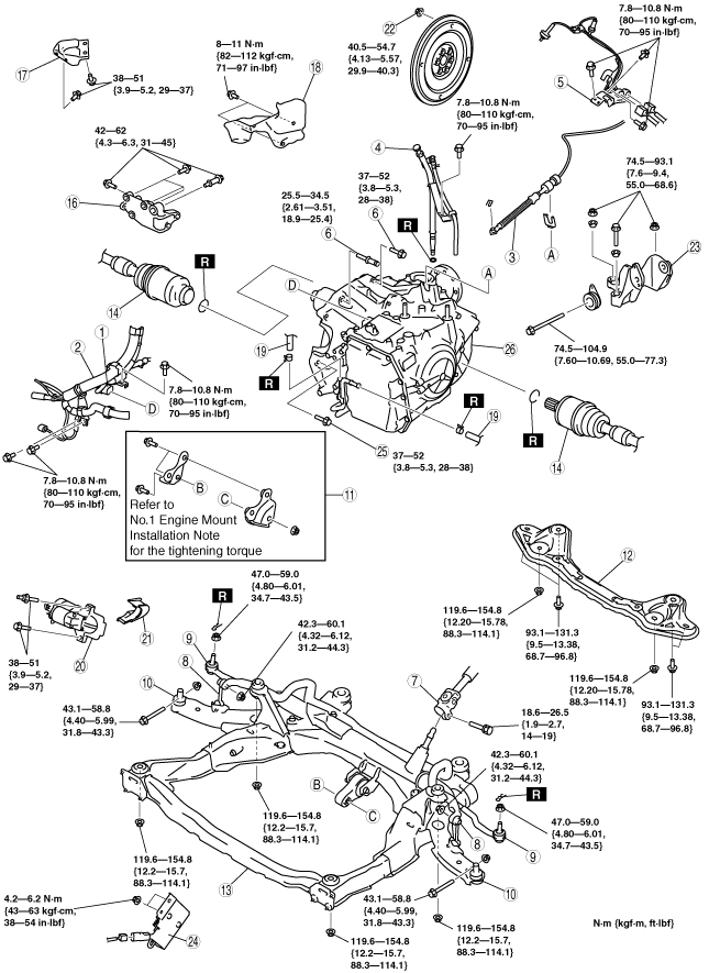
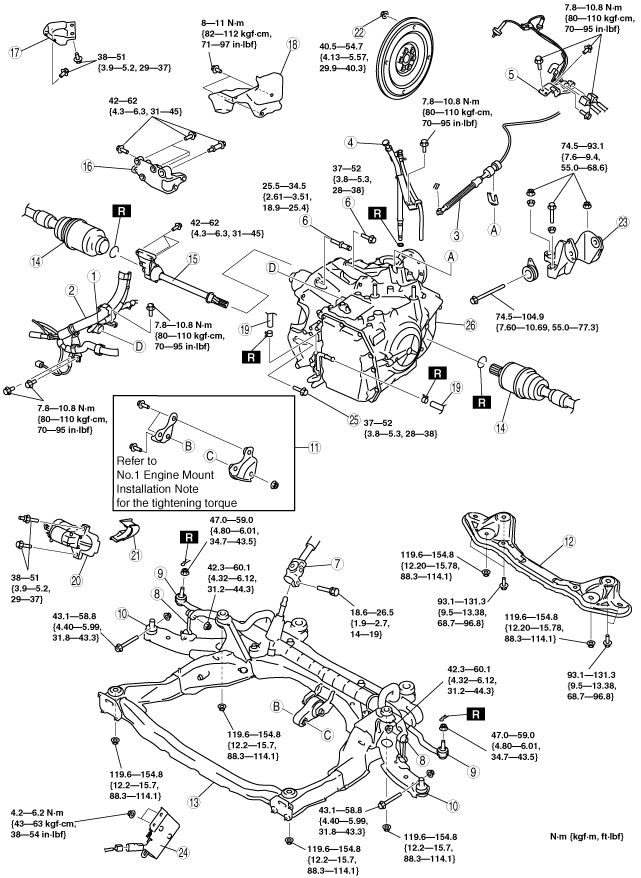
4. Remove in the order shown in the figure.
5. Install in the reverse order of removal.
6. Add ATF to the specified level. (See AUTOMATIC TRANSAXLE FLUID (ATF) REPLACEMENT [AW6A-EL, AW6AX-EL].)
7. Perform the mechanical system test. (See MECHANICAL SYSTEM TEST [AW6A-EL, AW6AX-EL].)
|
Service item |
Test item |
|||
|---|---|---|---|---|
|
Line pressure test |
Stall test |
Time lag test |
Time lag test |
|
|
ATX replacement
|
X
|
|
|
|
|
ATX overhaul
|
X
|
X
|
X
|
X
|
|
Torque converter replacement
|
X
|
X
|
|
|
|
Oil pump replacement
|
X
|
|
|
|
|
Control valve body component
|
X
|
|
|
|
|
Clutch system replacement
|
X
|
|
X
|
X
|
R.H.D.
acxaaw00000789
|
L.H.D.
acxaaw00000790
|
|
1
|
TCM connector
|
|
2
|
Wiring harness bracket
|
|
3
|
Selector cable
|
|
4
|
Oil filler tube, dipstick, breather hose
|
|
5
|
Wiring harness bracket (A/F sensor)
|
|
6
|
Transaxle mounting bolt (Upper side)
|
|
7
|
Steering shaft
|
|
8
|
Stabilizer control link
|
|
9
|
Tie-rod end ball joint
|
|
10
|
Lower arm ball joint
|
|
11
|
No.1 engine mount bracket
|
|
12
|
Crossmember bracket
|
|
13
|
Crossmember
|
|
14
|
Drive shaft
|
|
15
|
Joint shaft (2WD)
|
|
16
|
Transfer bracket (4WD)
|
|
17
|
WU-TWC bracket (4WD)
|
|
18
|
Heat shield (4WD)
|
|
19
|
Oil hose
|
|
20
|
Starter
|
|
21
|
Endplate cover
|
|
22
|
Torque converter installation nuts
|
|
23
|
No.4 engine mount bracket
|
|
24
|
Resistor
|
|
25
|
Transaxle mounting bolt (lower side)
|
|
26
|
Transaxle (2WD)
(See Transaxle Removal Note.)
(See Transaxle Installation Note.)
|
|
Transaxle, transfer and Joint shaft (4WD)
(See Transaxle Removal Note.)
(See Transaxle Installation Note.)
|
acxaaw00000791
|
|
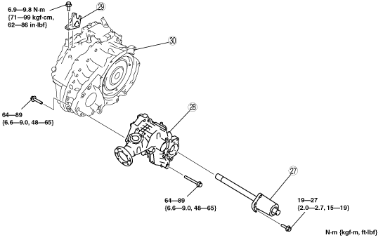
27
|
Joint shaft
|
|
28
|
Transfer
|
|
29
|
Cable bracket
|
|
30
|
Transaxle
|
Torque Converter Nuts Removal Note
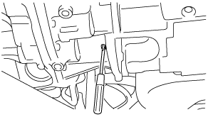
1. Align the holes by turning the torque converter.
2. Insert a flathead screwdriver through the converter housing service hole, and lock the drive plate.
acxaaw00000203
|
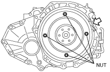
3. Remove the torque converter nuts.
acxaaw00000204
|
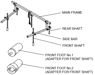
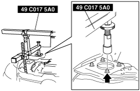
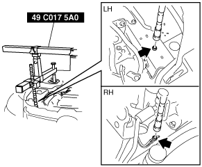
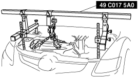
No.4 Engine Mount Bracket Removal Note
1. Install the SST using the following procedure.
acxaaw00000205
|
acxaaw00000206
|
acxaaw00000207
|
2. Support the engine using the SST.
acxaaw00000208
|
3. Remove the No.4 engine mount bracket.
Transaxle Removal Note
1. Support the transaxle on a jack.
acxaaw00000209
|
2. Remove the transaxle mounting bolts.
3. Remove the transaxle.
Transaxle Installation Note
1. Set the transaxle on a jack and lift it.
2. Install the transaxle mounting bolts.
acxaaw00000210
|
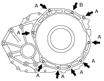
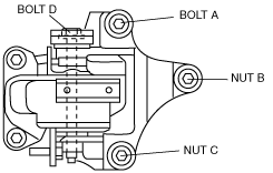
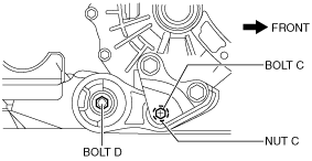
No.4 Engine Mount Bracket Installation Note
1. Install the No.4 engine mount bracket to the transaxle and temporarily tighten nuts
acxaaw00000211
|
2. Temporarily tighten bolt D.
3. Temporarily tighten bolt A and nuts B, C.
4. Tighten bolt A, nuts B and C in the order of B→A→C.
5. Tighten bolt D.
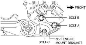
No.1 Engine Mount Installation Note
1. Install the No.1 engine mount bracket to the transaxle, then temporarily tighten bolts A and B.
acxaaw00001591
|
2. Install the No.1 engine mount rubber to the bracket, then temporarily tighten bolt C.
3. Tighten the No.1 engine mount bracket bolt A and B in order of A→B.
4. Fully tighten bolt C.
acxaaw00001621
|
Torque Converter Nuts Installation Note
1. Align the holes by turning the torque converter.
2. Insert a screwdriver through the converter housing service hole, and lock the drive plate.
acxaaw00000203
|
3. Tighten the torque converter mounting nuts.
acxaaw00000204
|
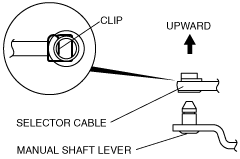
Selector Cable Installation Note
1. Install the selector lever to the manual shaft lever so that no load acts on the selector cable.
acxaaw00000213
|
2. Confirm that the tip of the manual shaft lever projects out of the end of the selector cable.