 |
acxuuw00000985
CLIMATE CONTROL UNIT INSPECTION [FULL-AUTO AIR CONDITIONER]
id0740a1802200
1. Remove the climate control unit. (See CLIMATE CONTROL UNIT REMOVAL/INSTALLATION [FULL-AUTO AIR CONDITIONER].)
2. Install the audio unit. (See AUDIO UNIT REMOVAL/INSTALLATION.)
3. Connect the climate control unit connector.
4. Connect the negative (-) lead of the tester to body ground.
5. Turn the ignition switch to the ON position.
6. By inserting the positive (+) lead of the tester into each climate control unit terminal, measure the voltage according to the terminal voltage table.
Terminal Voltage Table (Reference)
acxuuw00000985
|
|
Terminal |
Signal name |
Connected to |
Measurement condition |
Voltage (V) |
Inspection item (s) |
|---|---|---|---|---|---|
|
A
|
MS_CAN_L
|
CAN related module
|
Because this terminal is for communication, good/no good judgment by terminal voltage is not possible.
|
• Related wiring harness
|
|
|
B
|
MS_CAN_H
|
CAN related module
|
Because this terminal is for communication, good/no good judgment by terminal voltage is not possible.
|
• Related wiring harness
|
|
|
C
|
Sensor GND
|
• Ambient temperature sensor
• Cabin temperature sensor
• Evaporator temperature sensor
• Air mix actuator
• Airflow mode actuator
|
Under any condition
|
1.0 or less
|
• Climate control unit: terminal voltage (D)
|
|
D
|
GND
|
Body ground
|
Under any condition
|
1.0 or less
|
• Wiring harness: continuity (Climate control unit—GND: D—GND)
|
|
E
|
Solar radiation sensor input
|
Solar radiation sensor
|
60 W incandescent light shined from a distance of approx. 100 mm {3.9 in} directly on the solar radiation sensor
|
4.0
|
• Wiring harness: continuity (Climate control unit—solar radiation sensor: E—B, J—A)
• Climate control unit: terminal voltage (J)
• Solar radiation sensor
|
|
Blocking light to solar radiation sensor
|
0.1 or less
|
||||
|
F
|
Evaporator temperature sensor input
|
Evaporator temperature sensor
|
Compared with temperature detected by evaporator temperature sensor
|
Refer to graph 3
|
• Wiring harness: continuity (Climate control unit—evaporator temperature sensor: F—B, C—A)
• Wiring harness: short circuit (Climate control unit—evaporator temperature sensor: F—B)
• Evaporator temperature sensor
• Climate control unit: terminal voltage (D, M)
|
|
G
|
Rear window defroster switch
|
Rear window defroster relay
|
Rear window defroster switch OFF
|
B+
|
• Wiring harness: continuity, short circuit (Climate control unit—rear window defroster relay: G—E)
• Rear window defroster relay
|
|
Rear window defroster switch ON
|
0.05
|
• Climate control unit: terminal voltage (D, M)
• Climate control unit
|
|||
|
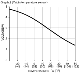
H
|
Cabin temperature sensor input
|
Cabin temperature sensor
|
Compared with temperature detected by cabin temperature sensor
|
Refer to graph 2
|
• Wiring harness: continuity (Climate control unit—cabin temperature sensor: H—B, C—A)
• Wiring harness: short circuit (Climate control unit—cabin temperature sensor: H—B)
• Cabin temperature sensor
• Climate control unit: terminal voltage (D, M)
|
|
I
|
Motor operation
|
Air intake actuator
|
Moving towards RECIRCULATE
|
10.75
|
• Wiring harness: continuity, short circuit (Climate control unit—air intake actuator: I—F, K—D)
• Air intake actuator
|
|
Moving towards FRESH
|
0.72
|
||||
|
J
|
+5V
|
• Air mix actuator
• Airflow mode actuator
• Solar radiation sensor
|
IG SW ON
|
5.08
|
• Wiring harness: short circuit
L.H.D.
(Climate control unit—air mix actuator, airflow mode actuator, solar radiation sensor: J—A, B, A)
R.H.D.
(Climate control unit—air mix actuator, airflow mode actuator, solar radiation sensor: J—B, B, A)
• Air mix actuator
• Airflow mode actuator
• Solar radiation sensor
• Climate control unit: terminal voltage (D, M)
|
|
IG SW OFF
|
1.0 or less
|
• Climate control unit replacement
|
|||
|
K
|
Motor operation
|
Air intake actuator
|
Moving towards FRESH
|
10.68
|
• Wiring harness: continuity, short circuit (Climate control unit—air intake actuator: K—D, I—F)
• Air intake actuator
|
|
Moving towards RECIRCULATE
|
0.68
|
||||
|
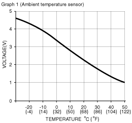
L
|
Ambient temperature sensor input
|
Ambient temperature sensor
|
Compared with temperature detected by ambient temperature sensor
|
Refer to graph 1
|
• Wiring harness: continuity (Climate control unit—ambient temperature sensor: C—A, L—B)
• Wiring harness: short circuit (Climate control unit—ambient temperature sensor: L—B)
• Ambient temperature sensor
• Climate control unit: terminal voltage (D, M)
|
|
M
|
IG2
|
A/C 10 A fuse
|
IG SW ON
|
B+
|
• Wiring harness: continuity, short circuit (Climate control unit— fuse: M—A/C 10 A)
• A/C 10 A fuse
|
|
IG SW OFF
|
1.0 or less
|
• Wiring harness: continuity, short circuit (Climate control unit— fuse: M—A/C 10 A)
|
|||
|
N
|
Potentiometer input
|
Air mix actuator
|
Set temperature at MAX COLD
|
0.73
|
• Wiring harness: continuity, short circuit (Climate control unit— air mix actuator: N—C)
• Air mix actuator
• Climate control unit: terminal voltage (J)
|
|
Set temperature at MAX HOT
|
4.38
|
||||
|
O
|
Motor operation
|
Airflow mode actuator
|
Moving towards VENT
|
10.66
|
• Wiring harness: continuity, short circuit (Climate control unit—airflow mode actuator: O—D, Q—F)
• Airflow mode actuator
|
|
Moving towards DEFROSTER
|
0.68
|
||||
|
P
|
Potentiometer input
|
Airflow mode actuator
|
VENT
|
4.38
|
• Wiring harness: continuity, short circuit (Climate control unit— airflow mode actuator: P—C)
• Airflow mode actuator
• Climate control unit: terminal voltage (J)
|
|
BILEVEL
|
3.51
|
||||
|
HEAT
|
2.59
|
||||
|
HEAT/DEF
|
1.67
|
||||
|
DEFROSTER
|
0.73
|
||||
|
Q
|
Motor operation
|
Airflow mode actuator
|
Moving towards DEFROSTER
|
10.43
|
• Wiring harness: continuity, short circuit (Climate control unit—airflow mode actuator: Q—F, O—D)
• Airflow mode actuator
|
|
Moving towards VENT
|
0.68
|
||||
|
R
|
B+
|
ROOM 15 A fuse
|
Under any condition
|
B+
|
• Wiring harness: continuity, short circuit (Climate control unit— fuse: R—ROOM 15 A)
• ROOM 15 A fuse
|
|
S
|
Motor operation
|
Air mix actuator
|
Moving towards HOT
|
10.44
|
• Wiring harness: continuity, short circuit
L.H.D.
(Climate control unit—air mix actuator: S—F, U—D)
R.H.D.
(Climate control unit—air mix actuator: S—D, U—F)
• Air mix actuator
|
|
Moving towards COLD
|
0.68
|
||||
|
T
|
Blower motor feed back
|
• Blower motor
• Power MOS FET
|
Fan stopped
|
12.09
|
1. Wiring harness: continuity, short circuit (Climate control unit—blower motor: T—A) (Climate control unit—power MOS FET: T—B, V—E) (Blower motor—blower relay: B—A) (Blower relay—fuse: D—BLOWER 40 A)
2. Wiring harness: continuity (Power MOS FET—body ground: A—GND) (Blower relay—ground: A—GND)
3. Power MOS FET
4. Blower motor
5. Blower relay
6. BLOWER 40 A fuse
7. A/C 10 A fuse
8. Power MOS FET replacement
|
|
Fan: manual LO
|
7.60
|
||||
|
Fan: manual HI
|
0.25
|
||||
|
U
|
Motor operation
|
Air mix actuator
|
Moving towards COLD
|
10.4
|
• Wiring harness: continuity, short circuit
L.H.D.
(Climate control unit—air mix actuator: U—D, S—F)
R.H.D.
(Climate control unit—air mix actuator: U—F, S—D)
• Air mix actuator
|
|
Moving towards HOT
|
0.68
|
||||
|
V
|
Blower fan speed control
|
Power MOS FET
|
Fan stopped
|
0.05
|
• Climate control unit: terminal voltage (T)
|
|
Fan: manual LO
|
3.02
|
||||
|
Fan: manual HI
|
7.77
|
||||
|
W
|
TNS signal
|
TNS relay
|
Headlight switch OFF
|
1.0 or less
|
• Wiring harness: short circuit (Climate control unit—TNS relay: W—C)
• TNS relay
• Headlight switch
|
|
Headlight switch ON
|
B+
|
• Wiring harness: continuity, short circuit (Climate control unit—TNS relay: W—C)
• TNS relay
• Headlight switch
|
|||
|
X
|
Illumination control
|
Instrument cluster
|
Headlight switch ON and panel light control switch at max
|
0.31
|
• Wiring harness: continuity (Climate control unit—instrument cluster: X—2H) (Instrument cluster—body ground: 2A—GND)
• Instrument cluster
|
|
Headlight switch ON and panel light control switch at min
|
9.56
|
• Wiring harness: short circuit (Climate control unit—instrument cluster: X—2H)
|
|||
 |
 |
 |
—
|