|
1
|
VERIFY OTHER RELATED DTCs
• Switch the ignition OFF, and then switch it ON (engine off or on).
• Display the DTCs using the M-MDS.
• Has DTC P057F:00 been recorded?
|
Yes
|
Repair the malfunctioning location according to the applicable DTC troubleshooting.
|
|
No
|
Go to the next step.
|
|
2
|
INSPECT BATTERY
• Switch the ignition OFF.
• Is the battery normal?
|
Yes
|
Go to the next step.
|
|
No
|
Recharge or replace the battery, then go to Step 8.
|
|
3
|
INSPECT DC-DC CONVERTER CONNECTOR CONDITION
• Switch the ignition OFF.
• Disconnect the DC-DC converter connector.
• Inspect the connector engagement and connection condition, and inspect the terminals for damage, deformation, corrosion, or disconnection.
• Is the connector normal?
|
Yes
|
Go to the next step.
|
|
No
|
Repair or replace the connector, then go to Step 8.
|
|
4
|
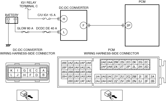
INSPECT DC-DC CONVERTER POWER SUPPLY CIRCUIT FOR OPEN CIRCUIT OR SHORT TO GROUND
• Verify that the DC-DC converter connector is disconnected.
• Measure the voltage at DC-DC converter terminal L (vehicle wiring harness side).
• Is the voltage B+?
|
Yes
|
Go to the next step.
|
|
No
|
Inspect the GLOW 80 A fuse and DCDC DE 40 A fuse.
• If the fuse is blown:
-
― Repair or replace the wiring harness which is shorted to ground.
― Replace the blown fuse.
• If the fuse is damaged:
-
― Replace the damaged fuse.
• If both fuses are normal:
-
― Repair or replace the wiring harness which has an open circuit.
Go to Step 8.
|
|
5
|
INSPECT DC-DC CONVERTER POWER SUPPLY CIRCUIT FOR OPEN CIRCUIT OR SHORT TO GROUND
• Verify that the DC-DC converter connector is disconnected.
• Switch the ignition ON (engine off).
• Measure the voltage at DC-DC converter terminal H (vehicle wiring harness side).
• Is the voltage B+?
|
Yes
|
Go to the next step.
|
|
No
|
Inspect the C/U IG1 15 A fuse.
• If the fuse is blown:
-
― Repair or replace the wiring harness which is shorted to ground.
― Replace the fuse.
• If the fuse is damaged:
-
― Replace the fuse.
• If the fuse is normal:
-
― Repair or replace the wiring harness which has an open circuit.
Go to Step 8.
|
|
6
|
INSPECT PCM CONNECTOR CONDITION
• Switch the ignition OFF.
• Disconnect the PCM connector.
• Inspect the connector engagement and connection condition, and inspect the terminals for damage, deformation, corrosion, or disconnection.
• Is the connector normal?
|
Yes
|
Go to the next step.
|
|
No
|
Repair or replace the connector, then go to Step 8.
|
|
7
|
INSPECT DC-DC CONVERTER
• Inspect the DC-DC converter.
• Is the DC-DC converter normal?
|
Yes
|
Replace the current sensor, then go to the next step.
|
|
No
|
Replace the DC-DC converter, then go to the next step.
|
|
8
|
VERIFY THAT REPAIRS HAVE BEEN COMPLETED
• Reconnect all the disconnected connectors.
• Refer to the [MEMORY CLEARING PROCEDURE] and clear the DTC.
• Perform the KOER self-test.
• Has DTC P0A8D:00 been recorded?
|
Yes
|
Repeat the inspection from Step 1.
• If the malfunction recurs, replace the PCM, then go to the next step.
|
|
No
|
Go to the next step.
|
|
9
|
VERIFY OTHER DTCs
• Has any other DTC or pending code been stored?
|
Yes
|
Repair the malfunctioning location according to the applicable DTC troubleshooting.
|
|
No
|
DTC troubleshooting completed.
|