 |
ac5uuw00007425
BATTERY REMOVAL/INSTALLATION [SKYACTIV-G 2.5]
id0117008005h8
Operation After Replacing Battery
|
Step |
Action |
|---|---|
|
1
|
Close the all doors.
|
|
2
|
Switch the ignition ON (engine off).
|
|
3
|
If a warning message is displayed in the screen display, clear the screen using the INFO switch and then go to the next step.
|
|
4
|
Shift the selector lever to the N position.
|
|
5
|
Perform the following work with the brake pedal depressed.
1. Depress the accelerator pedal for 5 s or more.
2. Verify that a warning message (master warning light) on the screen display flashes.
3. Depress and release the accelerator pedal 3 times.
4. Verify that a warning message (master warning light) on the screen display turn off.
|
|
6
|
Switch the ignition off and disconnect the negative battery terminal. (See NEGATIVE BATTERY TERMINAL DISCONNECTION/CONNECTION.)
|
|
7
|
Verifying battery condition initialization setting (i-stop setting). (See BATTERY CONDITION INITIALIZATION SETTING (i-stop SETTING).)
|
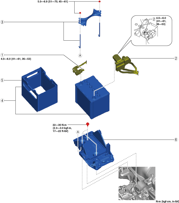
Battery Removal/Installation
1. Remove in the order indicated in the table.
2. Install in the reverse order of removal.
ac5uuw00007425
|
|
1
|
Negative battery terminal
|
|
2
|
Positive battery terminal
|
|
3
|
Battery clamp
|
|
4
|
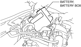
Battery, battery box
|
|
5
|
Battery box
|
|
6
|
Battery tray
(See Battery tray removal note.)
|
Battery, battery box removal note
1. Remove the battery with the battery box while the battery is positioned at an angle as shown in the figure.
ac5uuw00002434
|
Battery tray removal note
1. Remove the air cleaner component. (See INTAKE-AIR SYSTEM REMOVAL/INSTALLATION [SKYACTIV-G 2.5].)
2. Remove the PCM component. (See PCM REMOVAL/INSTALLATION [SKYACTIV-G 2.5].)
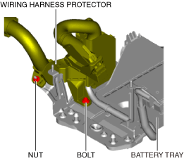
3. Remove the bolt and nut shown in the figure.
ac5uuw00007426
|
4. Remove the battery tray installation bolts.
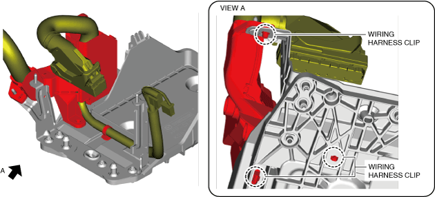
5. Remove the wiring harness clips shown in the figure.
ac5uuw00007427
|
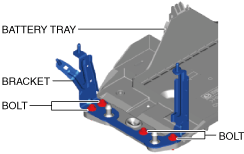
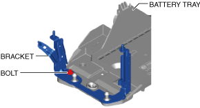
6. When replacing the battery tray with a new one, remove the bracket shown in the figure.
ac5uuw00007428
|
Battery tray installation note
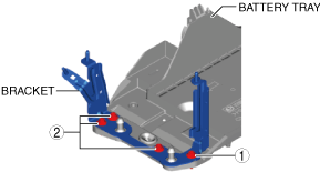
1. When replacing the battery tray with a new one, install the bracket using the following procedure:
ac5uuw00007429
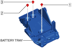
|
ac5uuw00007430
|
2. Tighten the battery tray installation bolts in the order shown in the figure.
ac5uuw00007431
|
3. Install the wiring harness clips shown in the figure.
ac5uuw00007427
|
4. Tighten the bolt and nut shown in the figure.
ac5uuw00007426
|
5. Install the PCM component. (See PCM REMOVAL/INSTALLATION [SKYACTIV-G 2.5].)
6. Install the air cleaner component. (See INTAKE-AIR SYSTEM REMOVAL/INSTALLATION [SKYACTIV-G 2.5].)
Battery box installation note
1. Install the battery box so that the side with the larger notch is pointed at the engine.
ac5uuw00007812
|