49 U043 004A
Oil pressure gauge
(Part of 49 U043 0A0A)

49 U043 005
Joint
(Part of 49 U043 0A0A)
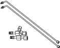
49 U043 006
Hose
(Part of 49 U043 0A0A)
POWER BRAKE UNIT INSPECTION
id041100883000
Special Service Tool (SST)
|
49 U043 004A
Oil pressure gauge
(Part of 49 U043 0A0A)
|
|
49 U043 005
Joint
(Part of 49 U043 0A0A)
|
|
49 U043 006
Hose
(Part of 49 U043 0A0A)
|
|
Without Using SST
Operation inspection
1. With the engine stopped, pump the pedal a few times.
2. With the pedal depressed, start the engine.
3. If the pedal moves down slightly immediately after starting the engine, the unit is normal.
Vacuum function inspection
1. Start the engine.
2. Stop the engine after driving the vehicle for 1—2 min.
3. Depress the pedal with normal force.
4. If the first pedal stroke is long and becomes shorter with subsequent strokes, the unit is normal.
Vacuum loss function inspection
1. Start the engine.
2. Depress the pedal with normal force.
3. With the pedal depressed, stop the engine.
4. Hold the pedal depressed for approx. 30 s.
5. If the pedal height does not change during this time, the unit is normal.
Using SST
Preparation Before Inspection
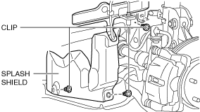
1. Remove the clips.
ac5uuw00007503
|
2. Set the splash shield aside.
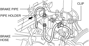
3. Disconnect the brake pipe from the brake hose (LF).
ac5uuw00007504
|
4. Remove the clips.
5. Remove the brake hose from the bracket.
6. Remove the brake pipe from the pipe holder.
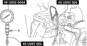
7. Install the SSTs to the brake pipe as shown in the figure.
ac5jjw00010685
|
8. Perform air bleeding of the SST and the brake line from bleeder screw A.
9. Install the pedal force gauge to the brake pedal.
10. Connect the vacuum gauge to the vacuum piping.
Vacuum loss inspection
1. Start the engine.
2. Depress the brake pedal with a force of 200 N {20.4 kgf, 45.0 lbf}..
3. Stop the engine when the vacuum gauge reading reaches 68 kPa {510 mmHg, 20 inHg} with the pedal depressed.
4. Measure the amount of vacuum decrease for 15 s immediately after stopping the engine.
5. If the gauge indicates a drop of 3.3 kPa {25 mmHg, 0.97 inHg} or less,, the unit is normal.
Non-boost operation inspection
1. If the pedal force and fluid pressure correlation is within the standard with the engine stopped and a vacuum amount of 0 kPa {0 mmHg, 0 inHg}, the system is normal.
Power brake unit Non-boost operation standard
|
Vacuum amount at 0 kPa {0 mmHg, 0 inHg} |
|
|---|---|
|
Pedal force |
Fluid pressure |
|
200 N {20.4 kgf, 45.0 lbf}
|
770 kPa {7.85 kgf/cm2, 112 psi} or more
|
Boost operation inspection
1. Start the engine and depress the brake pedal when the vacuum reaches 66.7 kPa {500 mmHg, 19.7 inHg}.
2. At this time, apply the indicated pedal force and if the fluid pressure is within the standard, the unit is normal.
Power brake unit boost operation standard
|
Vacuum amount at 66.7 kPa {500 mmHg, 19.7 inHg} |
|
|---|---|
|
Pedal force |
Fluid pressure |
|
200 N
|
7,640 kPa {77.91 kgf/cm2, 1108 psi} or more
|
Operation After Inspection
1. After inspection, remove the SST and install the brake hose, brake pipe, and the splash shield to their original positions. (See FRONT BRAKE HOSE REMOVAL/INSTALLATION.)
2. Bleed the air from the brake line. (See BRAKE FLUID AIR BLEEDING.)