 |
ac5wzw00009812
POWER BRAKE UNIT REMOVAL/INSTALLATION [R.H.D.]
id041100801852
Replacement part
|
Pipe holder
Quantity: 1
Location of use: Brake pipe
|
Gasket
Quantity: 1
Location of use: Power brake unit
|
Brake switch
Quantity: 1
Location of use: Brake pedal
|
Oil and chemical type
|
Brake fluid
Type: SAE J1703 or FMVSS116 DOT-3
|
1. Disconnect the negative battery terminal. (See NEGATIVE BATTERY TERMINAL DISCONNECTION/CONNECTION.)
2. Remove the following parts.
3. Remove the master cylinder. (See MASTER CYLINDER REMOVAL/INSTALLATION [R.H.D.].)
4. Remove the power brake unit vacuum sensor. (See POWER BRAKE UNIT VACUUM SENSOR REMOVAL/INSTALLATION [R.H.D.].)
5. Remove the washer tank bracket. (See WASHER TANK REMOVAL/INSTALLATION.)
6. Remove front under cover No.2. (SKYACTIV-D 2.2) (See FRONT UNDER COVER No.2 REMOVAL/INSTALLATION.)
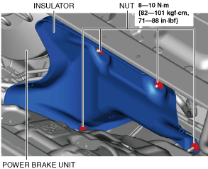
7. Remove the insulator.
ac5wzw00009812
|
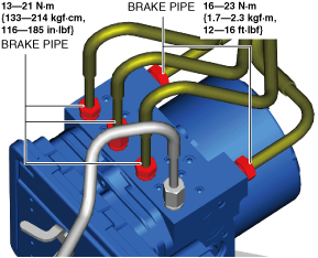
8. Disconnect the brake pipes from the DSC HU/CM.
ac5wzw00009813
|
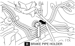
9. Disconnect the brake pipe holder from the vehicle.
ac8wzw00003227
|
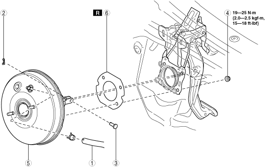
10. Remove in the order shown in the figure.
11. Install in the reverse order of removal.
12. After installation, add brake fluid and perform the air bleeding/fluid leakage inspection. (See BRAKE FLUID AIR BLEEDING.)
13. Remove the brake switch. (See BRAKE PEDAL REMOVAL/INSTALLATION [R.H.D.].)
14. Inspect the brake pedal. (See BRAKE PEDAL INSPECTION.)
15. Install a new brake switch. (See BRAKE PEDAL REMOVAL/INSTALLATION [R.H.D.].)
ac5wzw00009815
|
|
1
|
Vacuum hose
|
|
2
|
Snap pin
|
|
3
|
Clevis pin
|
|
4
|
Nut
|
|
5
|
Power brake unit
|
|
6
|
Gasket
|