49 F027 003
Handle
49 G030 796
Body (component part for 49 G030 795)

49 U034 204
Dust boot installer

OIL SEAL (CONTROL VALVE BODY) REPLACEMENT [GW6A-EL, GW6AX-EL]
id0517i2118700
Special service tool (SST)
|
49 F027 003
Handle
|
|
49 G030 796
Body (component part for 49 G030 795)
|
|
49 U034 204
Dust boot installer
|
|
Replacement part
|
Oil seal
Quantity: 1
Location of use: Control valve body
|
Hose clamp
Quantity: 1
Location of use: Control valve body
|
1. Disconnect the negative battery terminal. (See NEGATIVE BATTERY TERMINAL DISCONNECTION/CONNECTION.)
2. Remove the following parts as a single unit. (See INTAKE-AIR SYSTEM REMOVAL/INSTALLATION [SKYACTIV-D 2.2].)
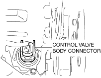
3. Disconnect the control valve body connector.
ac8wzw00001409
|
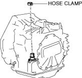
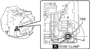
4. Remove the hose clamp.
ac8wzw00001410
|
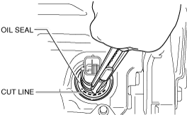
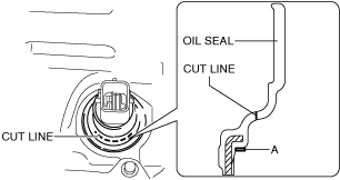
5. Cut the oil seal using a utility knife as shown in the figure.
ac8wzw00001411
|
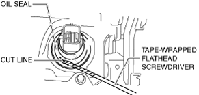
6. Remove the oil seal using a tape-wrapped flathead screwdriver.
ac8wzw00001412
|
ac8wzw00001413
|
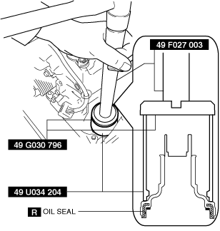
7. Temporarily install the oil seal (control valve body) by hand.
8. Install the oil seal (control valve body) using the SSTs and a hammer so that it does not tilt and the surface of the transaxle case and end surface of the oil seal (control valve body) are level.
ac8wzw00001414
|
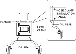
9. Install the new hose clamp to the position shown in the figure.
ac8wzw00001415
|
ac8wzw00001416
|
10. Connect the control valve body connector.
ac8wzw00001409
|
11. Install the following parts as a single unit. (See INTAKE-AIR SYSTEM REMOVAL/INSTALLATION [SKYACTIV-D 2.2].)
12. Connect the negative battery terminal. (See NEGATIVE BATTERY TERMINAL DISCONNECTION/CONNECTION.)