|
1
|
PERFORM ODDTC SELF TEST AND DTC INSPECTION
• Perform the ODDTC Self Test.
• Is the DTC displayed?
|
Yes
|
Go to the applicable DTC inspection.
|
|
No
|
Go to the next step.
|
|
2
|
INSPECT DOOR LATCH SWITCH STUCK OFF OR OPEN CIRCUIT
• Open each door and verify that the door ajar warning indication in the instrument cluster indicates.
• Does the door ajar warning indication indicate?
|
Yes
|
Go to the next step.
|
|
No
|
• Inspect the door latch switch on the door in which the ajar warning indication did not indicate and for an open circuit in the wiring harness between the rear body control module (RBCM) and ground.
• After inspection, go to Step 10.
|
|
3
|
DETERMINE IF MALFUNCTION CAUSE IS DOOR LOCK ACTUATOR
• Perform the lock/unlock operation using door lock switch for each door.
• Is door locked/unlocked?
|
Yes
|
Go to the next step.
|
|
No
|
• Inspect the door lock actuator for the door which could not lock/unlock.
• After inspection, go to Step 10.
|
|
4
|
DETERMINE IF MALFUNCTION CAUSE IS DOOR KEY CYLINDER
• Insert the auxiliary key into the door key cylinder and perform the lock/unlock operation using the auxiliary key.
• Is door locked/unlocked?
|
Yes
|
Go to the next step.
|
|
No
|
• Inspect the front door key cylinder switch.
• After inspection, go to Step 10.
|
|
5
|
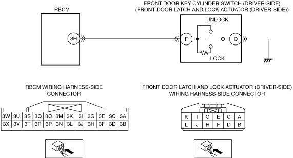
INSPECT IF MALFUNCTION CAUSE IS OPEN CIRCUIT IN WIRING HARNESS BETWEEN FRONT DOOR KEY CYLINDER SWITCH AND REAR BODY CONTROL MODULE (RBCM)
• Disconnect the negative battery terminal.
• Disconnect the front door latch and lock actuator (driver-side) connector.
• Disconnect the rear body control module (RBCM) connector.
• Inspect for continuity between the following terminals (vehicle wiring harness).
-
― Front door latch and lock actuator (driver-side) terminal H (L.H.D.)/F (R.H.D.) and rear body control module (RBCM) terminal 3H
• Is there continuity?
|
Yes
|
Go to the next step.
|
|
No
|
• Repair or replace the wiring harness for an open circuit.
• After repair procedure, go to Step 10.
|
|
6
|
INSPECT IF MALFUNCTION CAUSE IS OPEN CIRCUIT IN WIRING HARNESS BETWEEN D.LOCK 25 A FUSE AND BACKUP POWER SUPPLY
• Disconnect the backup power supply connector.
• Inspect for continuity between the following terminals (vehicle wiring harness).
-
― D.LOCK 25 A fuse and backup power supply terminal C
• Is there continuity?
|
Yes
|
Go to the next step.
|
|
No
|
• Repair or replace the wiring harness for an open circuit.
• After repair procedure, go to Step 10.
|
|
7
|
INSPECT IF MALFUNCTION CAUSE IS OPEN CIRCUIT IN WIRING HARNESS BETWEEN BACKUP POWER SUPPLY AND REAR BODY CONTROL MODULE (RBCM)
• Disconnect the backup power supply connector.
• Inspect for continuity between the following terminals (vehicle wiring harness).
-
― Backup power supply terminal A and rear body control module (RBCM) terminal 2B
• Is there continuity?
|
Yes
|
Go to the next step.
|
|
No
|
• Repair or replace the wiring harness for an open circuit.
• After repair procedure, go to Step 10.
|
|
8
|
INSPECT D.LOCK 25 A FUSE CONDITION
• Is the fuse (D.LOCK 25 A fuse) normal?
|
Yes
|
Go to the next step.
|
|
No
|
Replace the D.LOCK 25 A fuse.
Go to the next step.
|
|
9
|
INSPECT BACKUP POWER SUPPLY
• Inspect the backup power supply.
• Is the backup power supply normal?
|
Yes
|
Go to the next step.
|
|
No
|
Replace the backup power supply.
Go to the next step.
|
|
10
|
VERIFY IF MALFUNCTION CAUSE WAS CORRECTED
• Has the malfunction symptom been eliminated?
|
Yes
|
Troubleshooting completed. (Explain the contents of the servicing to the customer.)
|
|
No
|
Verify the malfunction symptom in the symptom troubleshooting chart and perform the applicable other malfunction diagnosis.
|