INSTRUMENT CLUSTER INSPECTION
id092200010600
Using a speedometer tester
-
Caution
-
• When only the front or the rear wheels are driven using a speedometer tester, the DSC HU/CM may determine that the vehicle speed signal is in error and the engine cannot be stopped by the normal operation. If the engine cannot be stopped, perform an emergency engine stop operation. (See
SERVICE CAUTIONS.)
1. Adjust the tire pressure to the specification. (See WHEEL AND TIRE SPECIFICATION.)
2. Using a speedometer tester, verify that the values are as indicated in the table.
Type A
|
Speedometer indication (km/h)
|
Speedometer tester indication (km/h)
|
|
20
|
19.00—21.00
|
|
40
|
39.00—41.00
|
|
60
|
59.00—61.00
|
|
80
|
79.00—81.00
|
|
100
|
99.00—101.00
|
|
120
|
119.00—121.00
|
|
140
|
139.00—141.00
|
|
160
|
159.00—161.00
|
|
180
|
179.00—181.00
|
|
200
|
199.00—201.00
|
|
220
|
219.00—221.00
|
|
240
|
239.00—241.00
|
Type B
|
Speedometer indication (km/h)
|
Speedometer tester indication (km/h)
|
|
20
|
20.80—23.40
|
|
40
|
40.80—43.50
|
|
60
|
61.20—63.60
|
|
80
|
81.60—83.80
|
|
100
|
102.00—104.00
|
|
120
|
122.40—124.10
|
|
140
|
142.80—144.40
|
|
160
|
163.20—166.40
|
|
180
|
183.60—188.20
|
|
200
|
204.00—209.90
|
|
220
|
224.40—231.50
|
|
240
|
244.80—253.10
|
-
-
― PCM
― TCM
― DSC HU/CM
-
Using the M-MDS
1. Connect the M-MDS to the DLC-2.
2. After vehicle identification, select the following from the M-MDS initialization screen.
- (1) Select “Data logger”
-
- (2) Select “Module”
-
- (3) Select “IC”
-
3. Using the simulation function SPEEDOMTR, verify that the values are as indicated in the table.
|
M-MDS display
|
Tachometer display
|
|
60 km/h
|
Tachometer needle moves to approx. 54.0—58.8 km/h {33.6—36.5 mph}.
|
|
120 km/h
|
Tachometer needle moves to approx. 111.6—117.6 km/h {69.35—73.07 mph}.
|
|
Off
|
Tachometer needle moves to bottommost position.
|
-
• If the speedometer does not operate or the indication is not within the allowable range, inspect the related wiring harnesses.
-
Tachometer Inspection
-
Caution
-
• If the engine speed exceeds the allowable range, the engine could be damaged. Therefore, when inspecting the tachometer, do not allow the engine speed to exceed the allowable range indicated on the tachometer.
1. Connect the M-MDS to the DLC-2.
2. After vehicle identification, select the following from the M-MDS initialization screen.
- (1) Select “Data logger”
-
- (2) Select “Module”
-
- (3) Select “IC”
-
3. Using the simulation function TACHOMTR, verify that the values are as indicated in the table.
|
M-MDS display
|
Tachometer display
|
|
3000 RPM
|
Tachometer needle moves to approx. 3,150 rpm.
|
|
6000 RPM
|
Tachometer needle moves to approx. 6,120 rpm.
|
|
Off
|
Tachometer needle moves to bottommost position.
|
-
• If the tachometer does not operate or the indication is not within the allowable range, inspect the DTC inspection for the following module and the related wiring harnesses.
-
― PCM
-
LCD Inspection
1. Connect the M-MDS to the DLC-2.
2. After vehicle identification, select the following from the M-MDS initialization screen.
- (1) Select “Data logger”
-
- (2) Select “Module”
-
- (3) Select “IC”
-
3. Using the simulation function item LCD_SEG, verify that the LDC displays as shown in the following figure.
-
Warning/Indicator Light Illumination Inspection
1. Connect the M-MDS to the DLC-2.
2. After vehicle identification, select the following from the M-MDS initialization screen.
- (1) Select “Data logger”
-
- (2) Select “Module”
-
- (3) Select “IC”
-
3. Using the simulation function WL+IL, verify that the warning/indicator lights in the following table are illuminated.
-
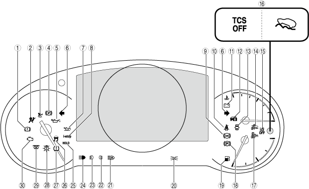
Type A
×: Applicable
—: Not applicable
|
No.
|
Warning light/Indicator light
|
Name
|
Message is displayed in multi-information display when warning/indicator light turns on/flashes
|
Message is displayed in center display when warning/indicator light turns on/flashes
|
Comment
|
Warning/indicator light turned on when ignition is switched ON (engine off or on)
|
|
1
|
 |
Brake system warning light
|
×
|
×
|
—
|
×
|
|
2
|
 |
Air bag/seat belt pre-tensioner system warning light
|
—
|
×
|
—
|
—
|
|
3
|
 |
Active bonnet warning light
|
×
|
×
|
With active bonnet
|
×
|
|
4
|
 |
Electric parking brake indicator light
|
×
|
—
|
—
|
—
|
|
5
|
 |
Engine oil warning light
|
×
|
×
|
—
|
×
|
|
6
|
 |
Direction indicator/hazard warning indicator lights
|
—
|
—
|
—
|
—
|
|
7
|
 |
Engine oil level warning light
|
×
|
×
|
With engine oil level sensor
|
—
|
|
8
|
 |
i-stop warning light (amber)/i-stop indicator light (green)
|
—
|
×
|
With i-stop system
|
×
|
|
9
|
 |
ABS warning light
|
—
|
×
|
—
|
×
|
|
10
|
 |
Seat belt warning light
|
—
|
—
|
—
|
—
|
|
11
|
 |
Charging system warning light
|
×
|
×
|
—
|
×
|
|
12
|
 |
Security indicator light
|
—
|
—
|
—
|
×
|
|
13
|
 |
Door-ajar warning light
|
—
|
—
|
—
|
—
|
|
14
|
 |
Smart brake support/smart city brake support (SBS/SCBS) OFF indicator light
|
—
|
—
|
With smart city brake support (SCBS) or smart brake support (SBS)
|
×
|
|
15
|
 |
Lane-keep assist system OFF indicator light/LDWS OFF indicator light
|
—
|
—
|
With lane departure warning system (LDWS) or lane-keep assist system
|
—
|
|
16
|
 |
TCS OFF indicator light
|
—
|
—
|
—
|
×
|
 |
Off-road traction assist indicator light
|
—
|
—
|
With off-road traction assist
|
×
|
|
17
|
 |
Blind spot monitoring (BSM) OFF indicator light
|
—
|
—
|
With blind spot monitoring (BSM) system
|
—
|
|
18
|
 |
Electric parking brake warning light
|
×
|
×
|
—
|
—
|
|
19
|
 |
Low fuel warning light
|
×
|
—
|
—
|
—
|
|
20
|
 |
Lights-on indicator light
|
×
|
—
|
—
|
—
|
|
21
|
 |
HBC indicator light (green)/HBC warning light (amber)/Adaptive LED headlights indicator light (green)/adaptive LED headlights warning light (amber)
|
×
|
×
|
With high beam control (HBC) system or adaptive LED headlights
|
×
|
|
22
|
 |
Rear fog light indicator light
|
—
|
—
|
With rear fog light
|
—
|
|
23
|
 |
Front fog light indicator light
|
—
|
—
|
With front fog light
|
—
|
|
24
|
 |
Headlight high-beam indicator light
|
—
|
—
|
—
|
—
|
|
25
|
 |
Mazda radar cruise control with stop & go function (MRCC with stop & GO function) indicator light
|
×
|
—
|
—
|
×
|
|
26
|
 |
TCS/DSC indicator light
|
—
|
×
|
—
|
×
|
|
27
|
 |
Tire pressure monitoring system warning light
|
×
|
×
|
—
|
×
|
|
28
|
 |
LED headlight warning light
|
—
|
×
|
With headlight (LED type)
|
—
|
|
29
|
 |
Glow indicator light
|
—
|
—
|
SKYACTIV-D 2.2
|
—
|
|
30
|
 |
Check engine light
|
—
|
×
|
—
|
×
|
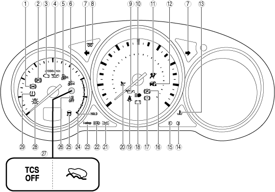
Type B
×: Applicable
—: Not applicable
|
No.
|
Warning light/Indicator light
|
Name
|
Message is displayed in multi-information display when warning/indicator light turns on/flashes
|
Message is displayed in center display when warning/indicator light turns on/flashes
|
Comment
|
Warning/indicator light turned on when ignition is switched ON (engine off or on)
|
|
1
|
|
ABS warning light
|
—
|
×
|
—
|
×
|
|
2
|
 |
Electric parking brake warning light
|
×
|
×
|
—
|
—
|
|
3
|
 |
Check engine light
|
—
|
×
|
—
|
×
|
|
4
|
|
Engine oil level warning light
|
×
|
×
|
With engine oil level sensor
|
—
|
|
5
|
|
Blind spot monitoring (BSM) OFF indicator light
|
×
|
×
|
—
|
—
|
|
6
|
 |
Smart brake support/smart city brake support (SBS/SCBS) OFF indicator light
|
—
|
—
|
With SBS/SCBS
|
×
|
|
7
|
 |
Direction indicator/hazard warning indicator lights
|
—
|
—
|
—
|
—
|
|
8
|
|
Glow indicator light
|
—
|
—
|
SKYACTIV-D 2.2
|
×
|
|
9
|
 |
Engine oil warning light
|
—
|
×
|
—
|
×
|
|
10
|
 |
Headlight high-beam indicator light
|
—
|
—
|
—
|
—
|
|
11
|
 |
Air bag/front seat belt pretensioner system warning light
|
—
|
×
|
—
|
×
|
|
12
|
 |
Security indicator light
|
—
|
—
|
—
|
×
|
|
13
|
 |
Low engine coolant temperature indicator light (blue)/high engine coolant temperature warning light (red)
|
×
|
×
|
—
|
×
|
|
14
|
|
Rear fog light indicator light
|
—
|
—
|
With rear fog light
|
—
|
|
15
|
|
Front fog light indicator light
|
—
|
—
|
With front fog light
|
—
|
|
16
|
|
Electric parking brake indicator light
|
×
|
—
|
—
|
—
|
|
17
|
|
Brake system warning light
|
—
|
×
|
—
|
×
|
|
18
|
 |
Charging system warning light
|
×
|
×
|
—
|
×
|
|
19
|
 |
Seat belt warning light
|
—
|
—
|
—
|
—
|
|
20
|
|
Active bonnet warning light
|
×
|
×
|
With active bonnet
|
×
|
|
21
|
 |
Lights-on indicator light
|
×
|
—
|
—
|
—
|
|
22
|
 |
HBC indicator light (green)/HBC warning light (amber)/Adaptive LED headlights indicator light (green)/adaptive LED headlights warning light (amber)
|
×
|
×
|
With high beam control (HBC) system or adaptive LED headlights
|
×
|
|
23
|
|
i-stop warning light (amber)/i-stop indicator light (green)
|
—
|
×
|
With i-stop system
|
×
|
|
24
|
|
Mazda Radar Cruise Control with stop & go function (MRCC with stop & go function) indicator light
|
—
|
—
|
With Mazda Radar Cruise Control with stop & go function (MRCC with stop & go function)
|
—
|
|
AUTOHOLD active indicator light
|
—
|
—
|
With AUTOHOLD
|
—
|
|
25
|
 |
TCS/DSC indicator light
|
—
|
×
|
—
|
×
|
|
26
|
|
Lane-keep assist system OFF indicator light/LDWS OFF indicator light
|
—
|
—
|
With lane departure warning system (LDWS) or lane-keep assist system
|
—
|
|
27
|
|
TCS OFF indicator light
|
—
|
—
|
—
|
×
|
|
Off-road traction assist indicator light
|
—
|
—
|
With off-road traction assist
|
×
|
|
28
|
 |
LED headlight warning light
|
—
|
×
|
—
|
—
|
|
29
|
 |
Tire pressure monitoring system warning light
|
×
|
×
|
With TPMS
|
×
|
Alarm Inspection
1. Connect the M-MDS to the DLC-2.
2. After vehicle identification, select the following from the M-MDS initialization screen.
- (1) Select “Data logger”
-
- (2) Select “Module”
-
- (3) Select “IC”
-
3. Using the simulation function ALARM, verify that the buzzer sounds.
-