-
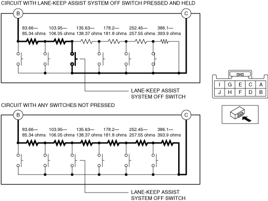
• Resistance with lane-keep assist system OFF switch pressed and held
-
― 187.61—191.39 ohms
-
-
• Resistance with any switches not pressed
-
― 1,139.99—1,163.01 ohms
-
ac5wzw00010275
|
LANE-KEEP ASSIST SYSTEM OFF SWITCH INSPECTION
id152000008900
10 Pin Type
Resistance inspection
1. Disconnect the negative battery terminal. (See NEGATIVE BATTERY TERMINAL DISCONNECTION/CONNECTION.)
2. Remove the following parts:
3. Measure the resistance between cluster switch terminals B and C under the following conditions:
ac5wzw00010275
|
LED illumination inspection
1. Disconnect the negative battery terminal. (See NEGATIVE BATTERY TERMINAL DISCONNECTION/CONNECTION.)
2. Remove the following parts:
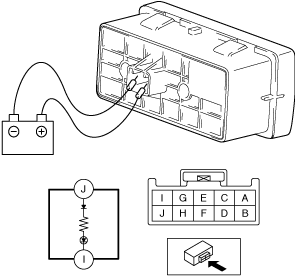
3. Apply battery positive voltage to cluster switch terminal J, and connect terminal I to ground.
am3uuw00010057
|
4. Verify that the LED illuminates.
14 Pin Type
Resistance inspection
1. Disconnect the negative battery terminal. (See NEGATIVE BATTERY TERMINAL DISCONNECTION/CONNECTION.)
2. Remove the following parts:
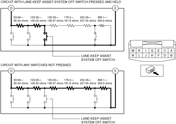
3. Measure the resistance between cluster switch terminals D and E under the following conditions:
ac8wzw00001531
|
LED illumination inspection
1. Disconnect the negative battery terminal. (See NEGATIVE BATTERY TERMINAL DISCONNECTION/CONNECTION.)
2. Remove the following parts:
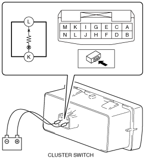
3. Apply battery positive voltage to cluster switch terminal L, and connect terminal K to ground.
ac8wzw00001532
|
4. Verify that the LED illuminates.