 |
ac5wzw00012699
360°VIEW MONITOR SWITCH INSPECTION
id152000009600
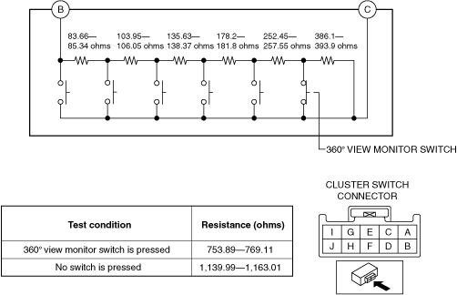
10 Pin Type
Resistance inspection
1. Disconnect the negative battery terminal. (See NEGATIVE BATTERY TERMINAL DISCONNECTION/CONNECTION.)
2. Remove the following parts:
3. Verify that the resistance between cluster switch terminals B and C is as indicated in the table.
ac5wzw00012699
|
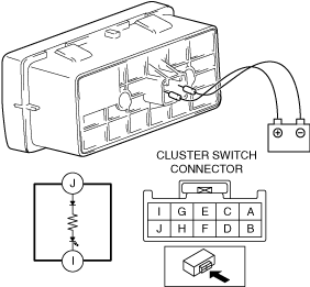
LED illumination inspection
1. Disconnect the negative battery terminal. (See NEGATIVE BATTERY TERMINAL DISCONNECTION/CONNECTION.)
2. Remove the following parts:
3. Apply battery positive voltage to cluster switch terminal J, and connect terminal I to ground.
ac5wzw00009887
|
4. Verify that the LED is turned on.
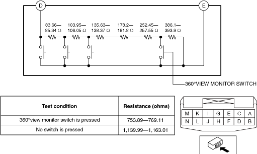
14 Pin Type
Resistance inspection
1. Disconnect the negative battery terminal. (See NEGATIVE BATTERY TERMINAL DISCONNECTION/CONNECTION.)
2. Remove the following parts:
3. Verify that the resistance between cluster switch terminals D and E is as indicated in the table.
ac8wzw00002220
|
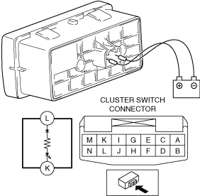
LED illumination inspection
1. Disconnect the negative battery terminal. (See NEGATIVE BATTERY TERMINAL DISCONNECTION/CONNECTION.)
2. Remove the following parts:
3. Apply battery positive voltage to cluster switch terminal L, and connect terminal K to ground.
ac8wzw00001245
|
4. Verify that the LED is turned on.