 |
adejjw00012514
FRONT STABILIZER INSTALLATION
id021300803500
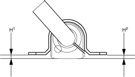
1. After installing the front stabilizer bracket, verify that the positions of the front stabilizer bracket and the front stabilizer bushing are within the range shown in the figure.
adejjw00012514
|
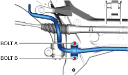
2. Temporarily tighten bolts A and B shown in the figure.
ac8wzw00001929
|
3. Tighten bolt B.
4. Tighten bolt A.
5. Tighten bolt B.
6. Install the front crossmember component. (See FRONT CROSSMEMBER REMOVAL/INSTALLATION.)
7. Assemble the intermediate shaft to the steering gear and linkage. (See STEERING WHEEL AND COLUMN REMOVAL/INSTALLATION.)
8. Install the joint cover. (See STEERING WHEEL AND COLUMN REMOVAL/INSTALLATION.)
9. Assemble the front lower arm ball joint to the steering knuckle. (See FRONT LOWER ARM REMOVAL/INSTALLATION.)
10. Assemble the outer ball joint to the steering knuckle. (See TIE-ROD END REPLACEMENT.)
11. Install the following parts.
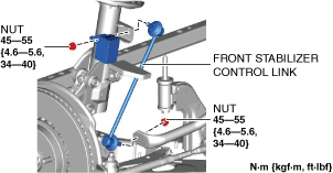
12. Install the front stabilizer control link.
ac8wzw00001930
|
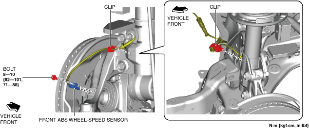
13. Install the front ABS wheel-speed sensor and the wiring harness clip as shown in the figure.
ac8wzw00001931
|
14. Install the wheels and tires. (See WHEEL AND TIRE REMOVAL/INSTALLATION.)