REAR AIR MIX ACTUATOR INSPECTION


id074000805900

Caution
•  If the lever position exceeds the operation range shown in the figure, the circuit in the actuator could be damaged. Always perform an actuator operation inspection with the lever movement within the range shown in the figure.

1.  Slide the front seat (RH) forward.

2.  Slide the front seat (RH) rearward approx. 50 mm {2.0 in}.

3.  Disconnect the negative battery terminal. (See NEGATIVE BATTERY TERMINAL DISCONNECTION/CONNECTION.)

4.  Remove the following parts:

(1)  Console side panel (See CONSOLE SIDE PANEL REMOVAL/INSTALLATION.)
(2)  Selector lever knob (See SELECTOR LEVER COMPONENT REMOVAL/INSTALLATION.)
(3)  Shift panel (See SHIFT PANEL REMOVAL/INSTALLATION.)
(4)  Front console box (without wireless charger (Qi)) (See FRONT CONSOLE BOX REMOVAL/INSTALLATION.)
(5)  Wireless charger (Qi) (with wireless charger (Qi)) (See WIRELESS CHARGER (Qi) REMOVAL/INSTALLATION.)
(6)  Side wall (See SIDE WALL REMOVAL/INSTALLATION.)
(7)  Rear console panel (See REAR CONSOLE PANEL REMOVAL/INSTALLATION.)
(8)  Rear cooler duct (See REAR COOLER DUCT REMOVAL/INSTALLATION.)
(9)  Rear console (See REAR CONSOLE REMOVAL/INSTALLATION.)

5.  Remove the rear air mix actuator. (See REAR AIR MIX ACTUATOR REMOVAL/INSTALLATION.)

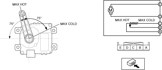
6.  Apply battery positive voltage and connect the ground to the rear air mix actuator terminals as indicated in the table below and verify the operation condition.

B+ Terminal

Ground Terminal

Operation

D
E
COLD → HOT
E
D
HOT → COLD

ac9wzw00005024

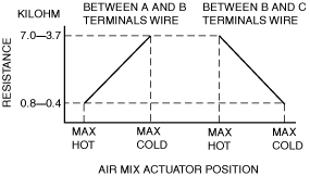
7.  Verify that the resistance between terminals A and B, B and C matches the rear air mix actuator operation as shown in the graph.

ac8wzw00001155

•  If the operation condition and resistance are not normal, replace the rear air mix actuator. (See REAR AIR MIX ACTUATOR REMOVAL/INSTALLATION.)