POWER LIFTGATE (PLG) DRIVE UNIT REMOVAL/INSTALLATION
id091100000800
Replacement part
|
Packing
Quantity: 1
Location of use: Power liftgate (PLG) drive unit
|
-
Warning
-
• If a malfunctioning power liftgate (PLG) drive unit is removed, the spring pressed into it may fly off and cause injury and damage to the vehicle. When removing a power liftgate (PLG) drive unit such as for one of the following malfunctions, perform the power liftgate (PLG) drive unit preparation. (See
Power Liftgate (PLG) Drive Unit Preparation.)
-
― The power liftgate (PLG) does not stop at the fully opened position and it gradually descends.
― The power liftgate (PLG) drive unit is deformed or damaged for some reason such as the vehicle was in an accident.
LH
1. Disconnect the negative battery terminal. (See NEGATIVE BATTERY TERMINAL DISCONNECTION/CONNECTION.)
2. Remove the following parts:
- (1) Rear scuff plate (See REAR SCUFF PLATE REMOVAL/INSTALLATION.)
-
- (2) Trunk board (See TRUNK BOARD REMOVAL/INSTALLATION.)
-
- (3) Trunk covering (See TRUNK COVERING REMOVAL/INSTALLATION.)
-
- (4) Trunk side pocket (See TRUNK SIDE POCKET REMOVAL/INSTALLATION.)
-
- (5) Trunk end trim (See TRUNK END TRIM REMOVAL/INSTALLATION.)
-
- (6) Bass-box (with Bose®) (See BASS-BOX REMOVAL/INSTALLATION.)
-
- (7) Third-row seat cushion (See THIRD-ROW SEAT CUSHION REMOVAL/INSTALLATION.)
-
- (8) Third-row seat back component (See THIRD-ROW SEAT BACK COMPONENT REMOVAL/INSTALLATION.)
-
- (9) Trunk side trim (See TRUNK SIDE TRIM REMOVAL/INSTALLATION.)
-
- (10) D-pillar trim (See D-PILLAR TRIM REMOVAL/INSTALLATION.)
-
- (11) C-pillar trim (See C-PILLAR TRIM REMOVAL/INSTALLATION.)
-
- (12) Assist handle (rear) (See ASSIST HANDLE REMOVAL/INSTALLATION.)
-
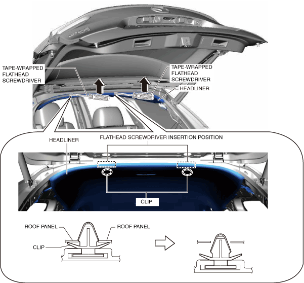
3. Insert a tape-wrapped flathead screwdriver into the position shown in the figure, move it in the direction of the arrow, and then detach the clips.
4. Partially peel back the headliner.
-
Caution
-
• Peeling back the headliner without supporting it may cause the headliner to bend excessively and crease. Peel back the headliner while supporting it.
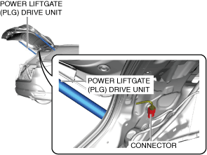
5. Disconnect the connector.
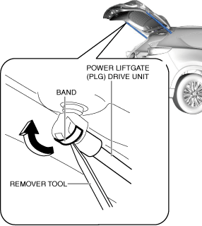
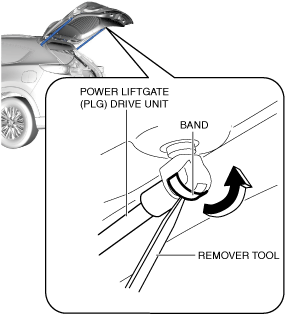
6. Insert the remover tool into the position shown in the figure.
-
Warning
-
• Remove the power liftgate (PLG) drive unit securing band using two people, one person supports the liftgate. If the power liftgate (PLG) drive unit securing band is removed without supporting the liftgate, it may fall off or close suddenly and cause injury.
7. Move the remover tool in the direction of the arrow shown in the figure and remove the securing band.
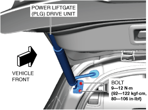
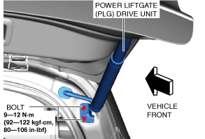
8. Remove the bolts.
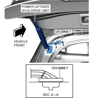
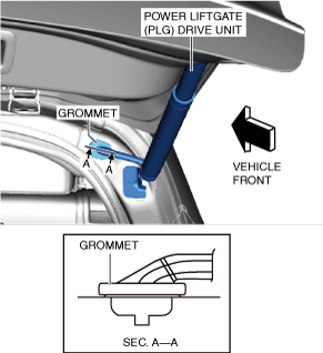
9. Remove the grommet from the body panel.
10. Remove the wiring harness from the body panel.
11. Remove the power liftgate (PLG) drive unit.
12. Install in the reverse order of removal. (See Power Liftgate (PLG) Drive Unit Installation Note.)
RH
1. Disconnect the negative battery terminal. (See NEGATIVE BATTERY TERMINAL DISCONNECTION/CONNECTION.)
2. Remove the following parts:
- (1) Rear scuff plate (See REAR SCUFF PLATE REMOVAL/INSTALLATION.)
-
- (2) Trunk board (See TRUNK BOARD REMOVAL/INSTALLATION.)
-
- (3) Trunk covering (See TRUNK COVERING REMOVAL/INSTALLATION.)
-
- (4) Trunk side pocket (See TRUNK SIDE POCKET REMOVAL/INSTALLATION.)
-
- (5) Trunk end trim (See TRUNK END TRIM REMOVAL/INSTALLATION.)
-
- (6) Bass-box (with Bose®) (See BASS-BOX REMOVAL/INSTALLATION.)
-
- (7) Third-row seat cushion (See THIRD-ROW SEAT CUSHION REMOVAL/INSTALLATION.)
-
- (8) Third-row seat back component (See THIRD-ROW SEAT BACK COMPONENT REMOVAL/INSTALLATION.)
-
- (9) Trunk side trim (See TRUNK SIDE TRIM REMOVAL/INSTALLATION.)
-
- (10) D-pillar trim (See D-PILLAR TRIM REMOVAL/INSTALLATION.)
-
- (11) C-pillar trim (See C-PILLAR TRIM REMOVAL/INSTALLATION.)
-
3. Disconnect the connector.
4. Insert the remover tool into the position shown in the figure.
-
Warning
-
• Remove the power liftgate (PLG) drive unit securing band using two people, one person supports the liftgate. If the power liftgate (PLG) drive unit securing band is removed without supporting the liftgate, it may fall off or close suddenly and cause injury.
5. Move the remover tool in the direction of the arrow shown in the figure and remove the securing band.
6. Remove the bolts.
7. Remove the grommet from the body panel.
8. Remove the wiring harness from the body panel.
9. Remove the power liftgate (PLG) drive unit.
10. Install in the reverse order of removal. (See Power Liftgate (PLG) Drive Unit Installation Note.)
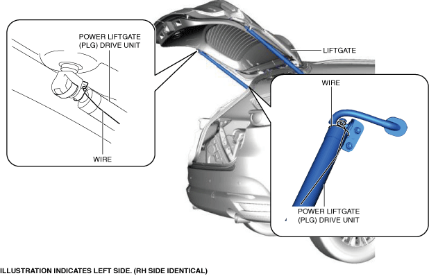
Power Liftgate (PLG) Drive Unit Preparation
1. Secure the power liftgate (PLG) drive unit with wire wrapped around both ends of the power liftgate (PLG) drive unit to prevent it from extending.
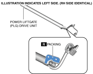
Power Liftgate (PLG) Drive Unit Installation Note
1. If the power liftgate (PLG) drive unit is to be reused, perform the following procedure.
- (1) Remove the packing remaining on the power liftgate (PLG) drive unit.
-
- (2) Apply new packing to the position shown in the figure.
-