 |
ac5wzw00005108
REAR MOUNT CAMERA INSPECTION
id092000815000
Type-A
Without 360°view monitor system
1. Disconnect the negative battery terminal. (See NEGATIVE BATTERY TERMINAL DISCONNECTION/CONNECTION.)
2. Remove the following parts:
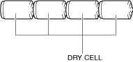
3. Prepare four dry cell batteries (1.5 V)
4. Connect the four dry cell batteries in a series.
ac5wzw00005108
|
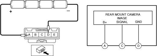
5. Connect the positive pole of the dry cell battery to rear mount camera terminal A, and the negative pole to terminal D.
ac8wzw00002215
|
6. With the cell batteries being connected, measure the waveform between rear mount camera terminal C and terminal D.
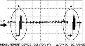
7. Verify that waveform A shown in the figure is displayed two times or more.
ac5wzw00010245
|
8. If the voltage is not as shown in the figure, replace the rear mount camera. (See REAR MOUNT CAMERA REMOVAL/INSTALLATION.)
With 360°view monitor system
1. Disconnect the negative battery terminal. (See NEGATIVE BATTERY TERMINAL DISCONNECTION/CONNECTION.)
2. Remove the following parts:
3. Prepare four dry cell batteries (1.5 V)
4. Connect the four dry cell batteries in a series.
ac5wzw00005108
|
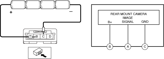
5. Connect the positive pole of the dry cell battery to rear mount camera terminal B, and the negative pole to terminal C.
ac8wzw00001263
|
6. With the cell batteries being connected, measure the waveform between rear mount camera terminal A and terminal C.
7. Verify that waveform A shown in the figure is displayed two times or more.
ac5wzw00010245
|
8. If the voltage is not as shown in the figure, replace the rear mount camera. (See REAR MOUNT CAMERA REMOVAL/INSTALLATION.)
Type-B
Without 360°view monitor system
1. Connect the M-MDS to the DLC-2.
2. Perform the DTC inspection for the connectivity master unit (CMU) and verify if any DTCs related to the rear mount camera is detected.
(Refer to the DTC INSPECTION [CONNECTIVITY MASTER UNIT (TYPE-B)] in the workshop manual)
With 360°view monitor system
1. Connect the M-MDS to the DLC-2.
2. Perform the DTC inspection for the 360°view monitor control module and verify if any DTCs related to the rear mount camera is detected. (With 360°VIEW MONITOR SYSTEM) (See DTC INSPECTION [360°VIEW MONITOR CONTROL MODULE (TYPE-B)].)