 |
ac8wzw00004650
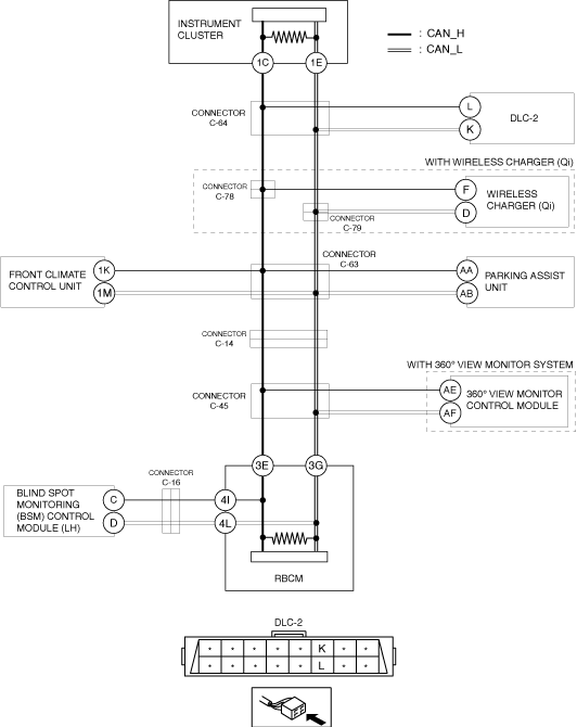
DETERMINING SHORT TO GROUND LOCATION (MS-CAN) [TYPE-A]
id100247000900
System Wiring Diagram
ac8wzw00004650
|
Determination Procedure
|
Step |
Inspection |
Action |
|
|---|---|---|---|
|
1
|
INSPECT FOR SHORT TO GROUND BETWEEN CONNECTOR C-64 AND REAR BODY CONTROL MODULE (RBCM)
• Disconnect the negative battery terminal.
• Disconnect connector C-64.
• Inspect for continuity at the following terminals:
• Is there continuity?
|
Yes
|
Go to Step 4.
|
|
No
|
Go to the next step.
|
||
|
2
|
INSPECT FOR SHORT TO GROUND BETWEEN CONNECTOR C-64 AND DLC-2
• Inspect for continuity at the following terminals:
• Is there continuity?
|
Yes
|
Repair or replace the wiring harness between connector C-64 and DLC-2 because the wiring harness is shorted to ground.
|
|
No
|
Go to the next step.
|
||
|
3
|
INSPECT CAN LINE IN INSTRUMENT CLUSTER FOR SHORT TO GROUND
• Disconnect the instrument cluster connector.
• Inspect for continuity at the following terminals:
• Is there continuity?
|
Yes
|
Repair or replace the wiring harness between the instrument cluster and connector C-64 because the wiring harness is shorted to ground.
|
|
No
|
Replace the instrument cluster because there is a short to ground in the instrument cluster.
|
||
|
4
|
INSPECT FOR SHORT TO GROUND BETWEEN CONNECTOR C-64 AND CONNECTORS C-78, C-79
• Disconnect connectors C-78, C-79.
• Connect connector C-64.
• Inspect for continuity at the following terminals:
• Is there continuity?
|
Yes
|
Repair or replace the wiring harness between connector C-64 and connectors C-78, C-79 because the wiring harness is shorted to ground.
|
|
No
|
Go to the next step.
|
||
|
5
|
INSPECT FOR SHORT TO GROUND BETWEEN CONNECTORS C-78, C-79 AND WIRELESS CHARGER (Qi)
• Inspect for continuity at the following terminals:
• Is there continuity?
|
Yes
|
Go to the next step.
|
|
No
|
Go to Step 7.
|
||
|
6
|
INSPECT CAN LINE IN WIRELESS CHARGER (Qi) FOR SHORT TO GROUND
• Disconnect the wireless charger (Qi) connector.
• Inspect for continuity at the following terminals:
• Is there continuity?
|
Yes
|
Repair or replace the wiring harness between wireless charger (Qi) and connectors C-78, C-79 because the wiring harness is shorted to ground.
|
|
No
|
Replace the wireless charger (Qi) because there is a short to ground inside the wireless charger (Qi).
|
||
|
7
|
INSPECT FOR SHORT TO GROUND BETWEEN CONNECTORS C-78, C-79 AND CONNECTOR C-63
• Disconnect connector C-63.
• Connect connectors C-78, C-79.
• Inspect for continuity at the following terminals:
• Is there continuity?
|
Yes
|
Repair or replace the wiring harness between connectors C-78, C-79 and connector C-63 because the wiring harness is shorted to ground.
|
|
No
|
Go to the next step.
|
||
|
8
|
INSPECT FOR SHORT TO GROUND BETWEEN CONNECTOR C-63 AND FRONT CLIMATE CONTROL UNIT
• Inspect for continuity at the following terminals:
• Is there continuity?
|
Yes
|
Go to the next step.
|
|
No
|
Go to Step 10.
|
||
|
9
|
INSPECT CAN LINE IN FRONT CLIMATE CONTROL UNIT FOR SHORT TO GROUND
• Disconnect the front climate control unit connector.
• Inspect for continuity at the following terminals:
• Is there continuity?
|
Yes
|
Repair or replace the wiring harness between the front climate control unit and connector C-63 because the wiring harness is shorted to ground.
|
|
No
|
Replace the front climate control unit because there is a short to ground in the front climate control unit.
|
||
|
10
|
INSPECT FOR SHORT TO GROUND BETWEEN CONNECTOR C-63 AND PARKING ASSIST UNIT
• Inspect for continuity at the following terminals:
• Is there continuity?
|
Yes
|
Go to the next step.
|
|
No
|
Go to Step 12.
|
||
|
11
|
INSPECT CAN LINE IN PARKING ASSIST UNIT FOR SHORT TO GROUND
• Disconnect the parking assist unit connector.
• Inspect for continuity at the following terminals:
• Is there continuity?
|
Yes
|
Repair or replace the wiring harness between the parking assist unit and connector C-63 because the wiring harness is shorted to ground.
|
|
No
|
Replace the parking assist unit because there is a short to ground in the parking assist unit.
|
||
|
12
|
INSPECT FOR SHORT TO GROUND BETWEEN CONNECTOR C-63 AND CONNECTOR C-14
• Disconnect connector C-14.
• Connect connector C-63.
• Inspect for continuity at the following terminals:
• Is there continuity?
|
Yes
|
Repair or replace the wiring harness between connector C-63 and connector C-14 because the wiring harness is shorted to ground.
|
|
No
|
Go to the next step.
|
||
|
13
|
INSPECT FOR SHORT TO GROUND BETWEEN CONNECTOR C-14 AND CONNECTOR C-45
• Disconnect connector C-45.
• Connect connector C-14.
• Inspect for continuity at the following terminals:
• Is there continuity?
|
Yes
|
Repair or replace the wiring harness between connector C-14 and connector C-45 because the wiring harness is shorted to ground.
|
|
No
|
Go to the next step.
|
||
|
14
|
INSPECT FOR SHORT TO GROUND BETWEEN CONNECTOR C-45 AND 360° VIEW MONITOR CONTROL MODULE
• Inspect for continuity at the following terminals:
• Is there continuity?
|
Yes
|
Go to the next step.
|
|
No
|
Go to Step 16.
|
||
|
15
|
INSPECT CAN LINE IN 360° VIEW MONITOR CONTROL MODULE FOR SHORT TO GROUND
• Disconnect the 360° view monitor control module connector.
• Inspect for continuity at the following terminals:
• Is there continuity?
|
Yes
|
Repair or replace the wiring harness between the 360° view monitor control module and connector C-45 because the wiring harness is shorted to ground.
|
|
No
|
Replace the 360° view monitor control module because there is a short to ground in the 360° view monitor control module.
|
||
|
16
|
INSPECT FOR SHORT TO GROUND BETWEEN CONNECTOR C-45 AND REAR BODY CONTROL MODULE (RBCM)
• Disconnect the rear body control module (RBCM).
• Connect connector C-45.
• Inspect for continuity at the following terminals:
• Is there continuity?
|
Yes
|
Repair or replace the wiring harness between the rear body control module (RBCM) and connector C-45 because the wiring harness is shorted to ground.
|
|
No
|
Go to the next step.
|
||
|
17
|
INSPECT FOR SHORT TO GROUND BETWEEN BLIND SPOT MONITORING (BSM) CONTROL MODULE (LH) AND REAR BODY CONTROL MODULE (RBCM)
• Inspect for continuity at the following terminals:
• Is there continuity?
|
Yes
|
Go to the next step.
|
|
No
|
Replace the rear body control module (RBCM) because there is a short to ground in the rear body control module (RBCM).
|
||
|
18
|
INSPECT FOR SHORT TO GROUND BETWEEN BLIND SPOT MONITORING (BSM) CONTROL MODULE (LH) AND CONNECTOR C-16
• Disconnect connector C-16.
• Inspect for continuity at the following terminals:
• Is there continuity?
|
Yes
|
Repair or replace the wiring harness between the rear body control module (RBCM) and connector C-16 because the wiring harness is shorted to ground.
|
|
No
|
Go to the next step.
|
||
|
19
|
INSPECT CAN LINE IN BLIND SPOT MONITORING (BSM) CONTROL MODULE (LH) FOR SHORT TO GROUND
• Disconnect the blind spot monitoring (BSM) control module (LH) connector.
• Connect connector C-16.
• Inspect for continuity at the following terminals:
• Is there continuity?
|
Yes
|
Repair or replace the wiring harness between the blind spot monitoring (BSM) control module (LH) and connector C-16 because the wiring harness is shorted to ground.
|
|
No
|
Replace the blind spot monitoring (BSM) control module (LH) because there is a short to ground in the blind spot monitoring (BSM) control module (LH).
|
||