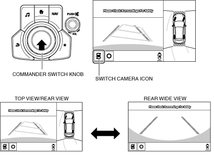
ac5wzn00004772
|
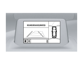
ac5wzn00004763
|
360°VIEW MONITOR SYSTEM
id151000004300
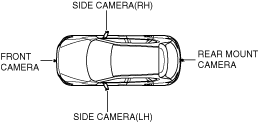
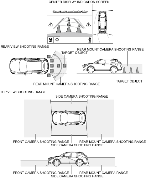
Outline
ac5wzn00004772
|
ac5wzn00004763
|
Functions
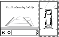
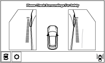
Top view
ac5wzn00004773
|
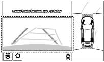
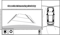
Front view
ac5wzn00004774
|
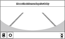
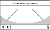
Front wide view
ac5wzn00004775
|
Side view
ac5wzn00004776
|
Rear view
ac5wzn00004777
|
Rear wide view
ac5wzn00004778
|
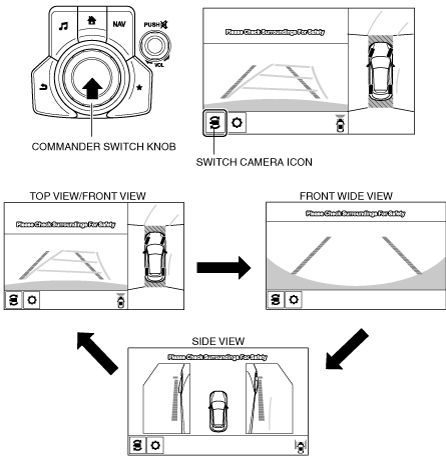
Screen display switching function
When top view/front view, front wide view, side view is displayed
ac5wzn00004779
|
When top view/rear view, rear wide view is displayed
ac5wzn00004780
|
Dynamic range correction function
Color brightness correction function
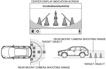
Parking sensor system
Rear Cross Traffic Alert (RCTA)
Malfunction indication function
Personalization feature
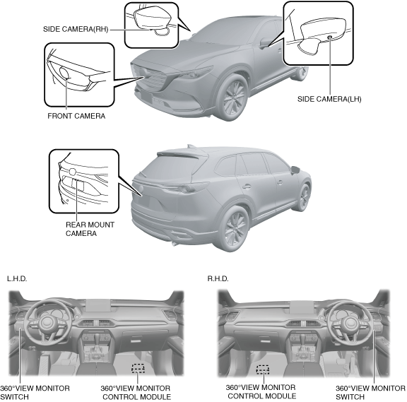
Structural View
ac9wzn00002022
|
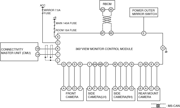
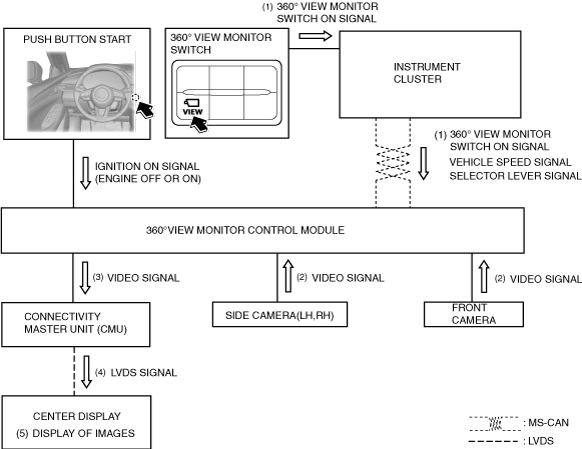
System diagram
am6xun00004253
|
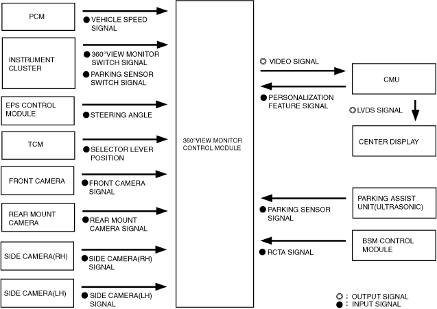
Block Diagram
ac5wzn00005121
|
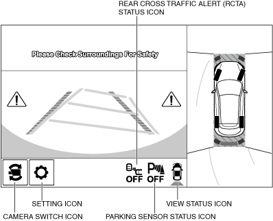
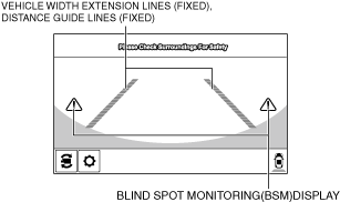
Screen Display
Icon display
Display example
ac5wzn00004782
|
|
Display/Icon
|
Content
|
|
View status icon
|
Indicates which image is displayed among the front view, front wide view, side view, rear view, and rear wide view.
|
|
Parking sensor status icon
|
Indicates that the parking sensor has a problem or the parking sensor system is switched off.
|
|
Rear Cross Traffic Alert (RCTA) status icon
|
Indicates that the blind spot monitoring (BSM) control module has a problem or the blind spot monitoring (BSM) system is switched off.
|
|
Switch camera icon
|
Switches the display screen each time the switch camera icon being displayed on the screen is touched.
|
|
Setting icon
|
Adjusts the image quality being displayed by the 360° view monitor system.
|
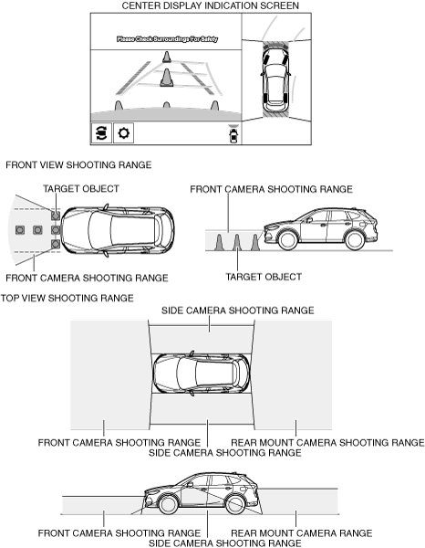
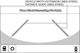
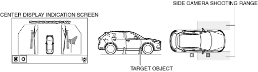
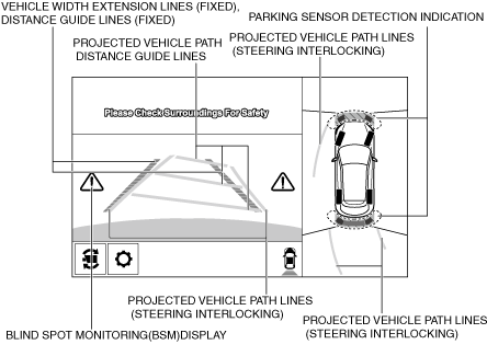
Top view/front view shooting range
Top view/front view shooting range
ac5wzn00004783
|
Top view/front view indication
am6xun00004277
|
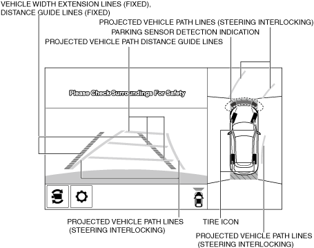
|
Display item |
Display line color |
Function |
|---|---|---|
|
Projected vehicle path distance guide lines (steering interlocking)
|
Red
|
Distance guide line indicating approx. 0.5 m from front end of front bumper
|
|
Yellow
|
Distance guide line indicating approx. 1.0 m from front end of front bumper
|
|
|
Yellow
|
Distance guide line indicating approx. 2.0 m from front end of front bumper
|
|
|
DISTANCE GUIDE LINES (FIXED)
|
Red
|
Distance guide line indicating approx. 0.5 m from front end of front bumper
|
|
Blue
|
Distance guide line indicating approx. 0.5-2.0 m from front end of front bumper
|
|
|
VEHICLE WIDTH EXTENSION LINES (FIXED)
|
Blue
|
Vehicle width extension guide line
|
|
PROJECTED VEHICLE PATH LINES (STEERING INTERLOCKING)
|
Yellow
|
Projected vehicle path calculated from steering angle
• Line indicating the path where the edge of the front bumper is expected to travel.
• Line indicating the path where the inner side of the vehicle is expected to travel.
|
|
TIRE ICON
|
—
|
Icon indicating tire direction
|
|
PARKING SENSOR DETECTION INDICATION
|
—
|
Icon indicating parking sensor detection/non-detection(See PARKING SENSOR SYSTEM.)
|
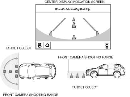
Front wide view
Front wide view shooting range
ac9wzn00002048
|
Front wide view display
ac5wzn00004786
|
|
Display item |
Display line color |
Function |
|---|---|---|
|
DISTANCE GUIDE LINES (FIXED)
|
Red
|
Distance guide line indicating approx. 0.5 m from front end of front bumperDistance guide line indicating approx. 0.5 m from front end of front bumper
|
|
Blue
|
Distance guide line indicating approx. 0.5-2.0 m from front end of front bumper
|
|
|
VEHICLE WIDTH EXTENSION LINES (FIXED)
|
Blue
|
Vehicle width extension guide line
|
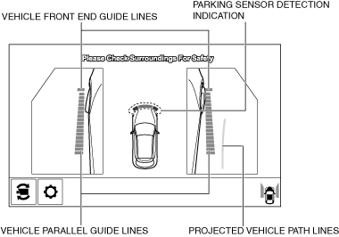
Side view
Side view shooting range
ac5wzn00004787
|
Side view display
ac9wzn00002049
|
|
Display item |
Display line color |
Function |
|---|---|---|
|
VEHICLE FRONT END GUIDE LINES
|
Blue
|
Distance guide line indicating approx. 0.25 m from front end of front bumper
|
|
VEHICLE PARALLEL GUIDE LINES
|
Blue
|
Line indicating the approximate vehicle width including the power outer mirror.
|
|
PROJECTED VEHICLE PATH LINES
|
Yellow
|
Projected vehicle path calculated from steering angle
|
|
PARKING SENSOR DETECTION INDICATION
|
—
|
Icon indicating parking sensor detection/non-detection(See PARKING SENSOR SYSTEM.)
|
Top view/rear view
Top view/rear view shooting range
ac5wzn00004788
|
Top view/rear view display
ac5wzn00005123
|
|
Display item |
Display line color |
Function |
|---|---|---|
|
Projected vehicle path distance guide lines (steering interlocking)
|
Red
|
Distance guide line indicating approx. 0.5 m from rear end of rear bumper
|
|
Yellow
|
Distance guide line indicating approx. 1.0 m from rear end of rear bumper
|
|
|
Yellow
|
Distance guide line indicating approx. 2.0 m from rear end of rear bumper
|
|
|
DISTANCE GUIDE LINES (FIXED)
|
Red
|
Distance guide line indicating approx. 0.5 m from rear end of rear bumper
|
|
Blue
|
Distance guide line indicating approx. 0.5-2.0 m from rear end of rear bumper
|
|
|
VEHICLE WIDTH EXTENSION LINES (FIXED)
|
Blue
|
Vehicle width extension guide line
|
|
PROJECTED VEHICLE PATH LINES (STEERING INTERLOCKING)
|
Yellow
|
Projected vehicle path calculated from steering angle
• Line indicating the path where the rear tire is expected to travel.
• Line indicating the path where the outer side of the vehicle is expected to travel.
|
|
TIRE ICON
|
—
|
Icon indicating tire direction
|
|
PARKING SENSOR DETECTION INDICATION
|
—
|
Icon indicating parking sensor detection/non-detection(See PARKING SENSOR SYSTEM.)
|
|
Rear Cross Traffic Alert (RCTA) display
|
—
|
Icon indicating Rear Cross Traffic Alert (RCTA) operation conditionBLIND SPOT MONITORING (BSM) SYSTEM)
|
Rear wide view
ac5wzn00004770
|
Rear wide view display
ac5wzn00005124
|
|
Display item |
Display line color |
Function |
|---|---|---|
|
DISTANCE GUIDE LINES (FIXED)
|
Red
|
Distance guide line indicating approx. 0.5 m from rear end of rear bumper
|
|
Blue
|
Distance guide line indicating approx. 0.5-2.0 m from rear end of rear bumper
|
|
|
VEHICLE WIDTH EXTENSION LINES (FIXED)
|
Blue
|
Vehicle width extension guide line
|
|
Rear Cross Traffic Alert (RCTA) display
|
—
|
Icon indicating Rear Cross Traffic Alert (RCTA) operation condition(See BLIND SPOT MONITORING (BSM) SYSTEM.)
|
Operation
Top view/front view, front wide view, side view display operation
1. When a 360° view monitor switch ON signal (1) is received with the operation conditions met, the 360° view monitor control module receives an image signal (2) from the front camera/side cameras (LH, RH)/rear mount camera.
2. The received image signal processes an image, and then the 360° view monitor control module sends (3) it to the CMU.
3. The CMU converts the received video signal to a LVDS signal and sends (4) the LVDS signal to the center display.
4. The center display indicates (5) the images at the area around the vehicle based on the LVDS signal received from the CMU.
5. When any of the following conditions is met, the 360° view monitor control module switches the images indicated on the center display to non-display.
ac9wzn00002047
|
Top view/rear view, rear wide view display operation
1. When a selector lever R position signal is received (1) with the operation conditions met, the 360° view monitor control module receives an image signal (2) from the front camera/side cameras (LH, RH)/rear mount camera.
2. The received image signal processes an image, and then the 360° view monitor control module sends (3) it to the CMU.
3. The CMU converts the received video signal to a LVDS signal (4) and sends the LVDS signal to the center display.(4)
4. The center display indicates (5) the images at the area around the vehicle based on the LVDS signal received from the CMU.
5. When the selector lever is in the P position, the 360° view monitor control module switches the images indicated on the center display to non-display.
ac9wzn00002023
|