|
1
|
VERIFY FREEZE FRAME DATA HAS BEEN RECORDED
• Has FREEZE FRAME DATA been recorded?
|
Yes
|
Go to the next step.
|
|
No
|
Record FREEZE FRAME DATA on the repair order, then go to the next step.
|
|
2
|
VERIFY RELATED SERVICE INFORMATION AVAILABILITY
• Verify related Service Information availability.
• Is any related Service Information available?
|
Yes
|
Perform repair or diagnosis according to the available Service Information.
• If the vehicle is not repaired, go to the next step.
|
|
No
|
Go to the next step.
|
|
3
|
VERIFY RELATED PENDING CODE OR STORED DTCs
• Turn the ignition switch off then to the ON position (Engine off).
• Verify related pending code or stored DTCs.
• Are other DTCs present?
|
Yes
|
Go to the appropriate DTC troubleshooting.
|
|
No
|
Go to the next step.
|
|
4
|
INSPECT CKP SENSOR SIGNAL SENT TO PCM
-
Note
-
• The battery should be fully charged and the starting system should be functioning properly.
• Turn the ignition switch to the ON position (Engine off)
• Access the PCM and monitor the RPM PID.
• Crank the engine.
• Is the engine speed more than 150 rpm?
|
Yes
|
Go to Step 13.
(The system is operating correctly at this time. The concern may have been caused by a loose or corroded connector.)
|
|
No
|
Go to the next step.
|
|
5
|
INSPECT TIMING COVER, CKP SENSOR AND EXTERNAL TRIGGER WHEEL (OUTSIDE TIMING COVER) FOR OBVIOUS PHYSICAL DAMAGE
• Turn the ignition switch off.
• Visually check the timing cover, CKP sensor and external trigger wheel (outside the timing cover) for obvious physical damage.
• Do any parts appear physically damaged?
|
Yes
|
Repair if necessary.
Then go to Step 13.
|
|
No
|
Go to Step.
|
|
6
|
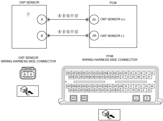
INSPECT FOR PROPER CKP BIAS VOLTAGES IN PCM
• Disconnect the CKP sensor connector.
• Turn the ignition switch to the ON position (Engine off)
• Measure the voltage between:
-
― CKP sensor terminal A on the wiring harness side and battery negative
― CKP sensor terminal B on the wiring harness side and battery negative
• Are the voltages between 1—3 V?
|
Yes
|
Go to the next step.
|
|
No
|
Go to Step 9.
|
|
7
|
INSPECT CKP SENSOR RESISTANCE
• CKP sensor connector is disconnected.
• Turn the ignition switch off.
• Measure the resistance between CKP sensor terminal A and B on the component side.
• Is the resistance between 575—790 ohms?
|
Yes
|
Go to the next step.
|
|
No
|
Replace the CKP sensor.
Then go to Step 13.
|
|
8
|
INSPECT CKP WIRING HARNESS SHIELD CIRCUIT FOR SHORT TO GROUND
-
Note
-
• The wiring harness shield protects the CKP signal from electrical noise and is grounded at one end, typically near the PCM.
-
Note
-
• Perform the following resistance measurement between the CKP shield and the ground.
• CKP sensor connector is disconnected.
• Measure the resistance between:
-
― CKP_SHLD assembly connector wiring harness side and ground
• Is the resistance less than 5 ohms?
|
Yes
|
Go to the next step.
|
|
No
|
Repair the short circuit.
Check for a poor ground.
Then go to Step 13.
|
|
9
|
INSPECT FOR SHORT BETWEEN CKP (+) AND CKP (-) IN WIRING HARNESS
• CKP sensor connector is disconnected.
• Turn the ignition switch off.
• Disconnect the PCM connector.
• Measure the resistance between:
-
― CKP sensor terminal A and B on the wiring harness side
• Is the resistance more than 10 kilohms?
|
Yes
|
Go to the next step.
|
|
No
|
Repair or replace suspected part, then go to Step 13.
|
|
10
|
INSPECT CKP CIRCUIT(S) FOR OPEN CIRCUIT IN WIRING HARNESS
• CKP sensor and PCM connectors are disconnected.
• Measure the resistance between:
-
― CKP sensor connector A on the wiring harness side and PCM terminal 2V
― CKP sensor connector B on the wiring harness side and PCM terminal 2R
• Are the resistances less than 5 ohms?
|
Yes
|
Go to the next step.
|
|
No
|
Repair or replace suspected part, then go to Step 13.
|
|
11
|
INSPECT CKP CIRCUIT(S) FOR SHORT TO GROUND IN WIRING HARNESS
• CKP sensor and PCM connectors are disconnected.
• Measure the resistance between:
-
― CKP sensor connector A on the wiring harness side and battery negative
― CKP sensor connector B on the wiring harness side and battery negative
• Are the resistances more than 10 kilohms?
|
Yes
|
Go to the next step.
|
|
No
|
Repair or replace suspected part, then go to Step 13.
|
|
12
|
INSPECT CKP CIRCUIT FOR SHORT TO VOLTAGE IN WIRING HARNESS
• CKP sensor and PCM connectors are disconnected.
• Turn the ignition switch to the ON position (Engine off).
• Measure the voltage between:
-
― CKP sensor connector A on the wiring harness side and battery negative
― CKP sensor connector B on the wiring harness side and battery negative
• Are any voltage present?
|
Yes
|
Repair or replace suspected part, then go to the next step.
|
|
No
|
Go to the next step.
(The system is operating correctly at this time. The concern may have been caused by a loose or corroded connector.)
|
|
13
|
VERIFY TROUBLESHOOTING OF DTC P0320:00 HAS BEEN COMPLETED
• Verify that all disconnected connectors are reconnected.
• Turn the ignition switch to the ON position (Engine off).
• Clear the DTC from the PCM memory using the M-MDS.
• Perform the KOER self-test.
• Is the PENDING CODE for this DTC present?
|
Yes
|
Repeat the inspection from Step 1.
• If the malfunction recurs, replace the PCM.
Go to the next step.
|
|
No
|
Go to the next step.
|
|
14
|
VERIFY AFTER REPAIR PROCEDURE
• Perform the “AFTER REPAIR PROCEDURE”.
• Are any DTCs present?
|
Yes
|
Go to the applicable DTC inspection.
|
|
No
|
Troubleshooting completed.
|