|
1
|
VERIFY FREEZE FRAME DATA HAS BEEN RECORDED
• Has FREEZE FRAME DATA been recorded?
|
Yes
|
Go to the next step.
|
|
No
|
Record FREEZE FRAME DATA on the repair order, then go to the next step.
|
|
2
|
VERIFY RELATED SERVICE INFORMATION AVAILABILITY
• Verify related Service Information availability.
• Is any related Service Information available?
|
Yes
|
Perform repair or diagnosis according to the available Service Information.
• If the vehicle is not repaired, go to the next step.
|
|
No
|
Go to the next step.
|
|
3
|
INSPECT FOR POWER SUPPLY IN WIRING HARNESS
• Turn the ignition switch off.
• Disconnect the A/F sensor connector.
• Turn the ignition switch to the ON position (engine off).
• Measure the voltage between suspect A/F sensor wiring harness-side connector terminal C and ground.
• Is the voltage greater than 10 V?
|
Yes
|
Turn the ignition switch off.
Go to the next step.
|
|
No
|
Inspect the ENG BAR fuse.
• If there is fuse deterioration, replace the fuse.
• If the fuse has melted, repair for short to ground and replace the fuse.
• If the fuse is normal, repair an open circuit.
Go to Step 9.
|
|
4
|
INSPECT A/F SENSOR HEATER CIRCUIT FOR OPEN CIRCUIT IN WIRING HARNESS
• A/F sensor connector is disconnected.
• Turn the ignition switch off.
• Disconnect the PCM connector.
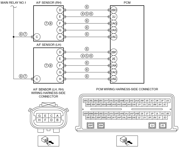
• Measure the resistance between the following terminals (wiring harness-side):
-
― P0053:00:
-
• A/F sensor (RH) terminal E—PCM terminal 2J
― P0059:00:
-
• A/F sensor (LH) terminal E—PCM terminal 2E
• Is the resistance less than 5 ohm?
|
Yes
|
Go to the next step.
|
|
No
|
Repair for an open circuit, then go to Step 9.
|
|
5
|
INSPECT A/F SENSOR HEATER CIRCUIT FOR SHORT CIRCUIT TO GROUND
• A/F sensor and PCM connectors are disconnected.
• Measure the resistance between suspect A/F sensor wiring harness-side connector terminal E and body ground.
• Is the resistance greater than 10 kilohms?
|
Yes
|
Go to the next step.
|
|
No
|
Repair a short to the ground circuit, then go to Step 9.
|
|
6
|
INSPECT A/F SENSOR HEATER CIRCUIT FOR SHORT CIRCUIT IN WIRING HARNESS
• A/F sensor and PCM connectors are disconnected.
• Measure the resistance between suspect A/F sensor wiring harness-side connector terminal E and the following terminals:
-
― A/F sensor wiring harness-side connector terminal D
― A/F sensor wiring harness-side connector terminal C
― A/F sensor wiring harness-side connector terminal F
― A/F sensor wiring harness-side connector terminal H
― A/F sensor wiring harness-side connector terminal G
• Is the resistance greater than 10 kilohms?
|
Yes
|
Go to the next step.
|
|
No
|
Repair for a short circuit, then go to Step 9.
|
|
7
|
INSPECT A/F SENSOR INTERNAL RESISTANCE OF A/F SENSOR HEATER
• A/F sensor and PCM connectors are disconnected.
• Measure the resistance between suspect A/F sensor connector terminal C and E on the component side.
• Is the resistance between 1—10 ohms?
|
Yes
|
Go to the next step.
|
|
No
|
Replace the suspect A/F sensor.
Go to Step 9.
|
|
8
|
INSPECT A/F SENSOR HEATER CIRCUIT FOR INTERNAL SHORT CIRCUIT TO GROUND
• A/F sensor and PCM connectors are disconnected.
• Measure the resistance between suspect A/F sensor component side connector terminal E and ground.
• Is the resistance greater than 10 kilohms?
|
Yes
|
Go to the next step.
(The system is operating normally at this time. The concern may have been caused by a loose or corroded connector.)
|
|
No
|
Replace the suspect A/F sensor.
Go to the next step.
|
|
9
|
VERIFY TROUBLESHOOTING OF DTC P0053:00, P0059:00 HAS BEEN COMPLETED
• Verify that all disconnected connectors are reconnected.
• Clear the DTC from the PCM memory using the M-MDS.
• Perform the KOEO or KOER self-test.
• Is the PENDING CODE for this DTC present?
|
Yes
|
Repeat the inspection from Step 1.
• If the malfunction recurs, replace the PCM.
Go to the next step.
|
|
No
|
Go to the next step.
|
|
10
|
VERIFY AFTER REPAIR PROCEDURE
• Perform the “AFTER REPAIR PROCEDURE”.
• Are any DTCs present?
|
Yes
|
Go to the applicable DTC inspection.
|
|
No
|
Troubleshooting completed.
|