DTC P2251:00
DTC P2254:00
P2251:00: A/F sensor (RH) negative current control circuit/open
P2254:00: A/F sensor (LH) negative current control circuit/open
DETECTION CONDITION
• P2251:00 indicates that A/F sensor (RH) positive current control circuit/open
• P2254:00 indicates that A/F sensor (LH) positive current control circuit/open
• The powertrain control module (PCM) monitors the universal heated oxygen sensor (HO2S) for a circuit concern. This DTC sets when the PCM detects a concern with the circuit used to determine the oxygen content in the exhaust gas.
POSSIBLE CAUSE
• Open A/F sensor circuit
• P2251:00:
-
― Open circuit in wiring harness between the following terminals:
-
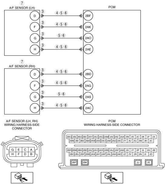
• A/F sensor (RH) terminal D—PCM terminal 2BD• A/F sensor (RH) terminal F—PCM terminal 2AG• A/F sensor (RH) terminal H—PCM terminal 2AC
― Short to ground in wiring harness between the following terminals:-
• A/F sensor (RH) terminal D—PCM terminal 2BD• A/F sensor (RH) terminal F—PCM terminal 2AG• A/F sensor (RH) terminal G—PCM terminal 2AS• A/F sensor (RH) terminal H—PCM terminal 2AC
― Short to power supply in wiring harness between the following terminals:-
• A/F sensor (RH) terminal D—PCM terminal 2BD• A/F sensor (RH) terminal F—PCM terminal 2AG• A/F sensor (RH) terminal G—PCM terminal 2AS• A/F sensor (RH) terminal H—PCM terminal 2AC
-
• P2254:00:
-
― Open circuit in wiring harness between the following terminals:
-
• A/F sensor (LH) terminal D—PCM terminal 2BF• A/F sensor (LH) terminal F—PCM terminal 2AK• A/F sensor (LH) terminal H—PCM terminal 2AE
― Short to ground in wiring harness between the following terminals:-
• A/F sensor (LH) terminal D—PCM terminal 2BF• A/F sensor (LH) terminal F—PCM terminal 2AK• A/F sensor (LH) terminal G—PCM terminal 2AO• A/F sensor (LH) terminal H—PCM terminal 2AE
― Short to power supply in wiring harness between the following terminals:-
• A/F sensor (LH) terminal D—PCM terminal 2BF• A/F sensor (LH) terminal F—PCM terminal 2AK• A/F sensor (LH) terminal G—PCM terminal 2AO• A/F sensor (LH) terminal H—PCM terminal 2AE
-
• Damaged A/F sensor
• PCM malfunction