VARIABLE VALVE TIMING ACTUATOR REMOVAL/INSTALLATION [MZI-3.7]
id0110c5801100
-
Warning
-
• Fuel vapor is hazardous. It can very easily ignite, causing serious injury and damage. Always keep sparks and flames away from fuel.
• Fuel line spills and leakage are dangerous. Fuel can ignite and cause serious injures or death and damage. Fuel can also irritate skin and eyes. To prevent this, always complete the “Fuel Line Safety Procedure”. (See
BEFORE SERVICE PRECAUTION [MZI-3.7].)
• Continuous exposure to USED engine oil has caused skin cancer in laboratory mice. Protect your skin by washing with soap and water immediately after working with engine oil.
-
Caution
-
• The variable valve timing actuator cannot be disassembled because it is a precision unit.
-
Note
-
• The following procedure “VARIABLE VALVE TIMING ACTUATOR REMOVAL/INSTALLATION” is performed after the engine and transaxle component is removed from the vehicle. (See
ENGINE REMOVAL/INSTALLATION [MZI-3.7].)
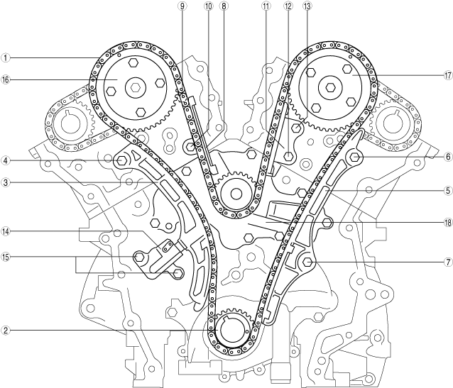
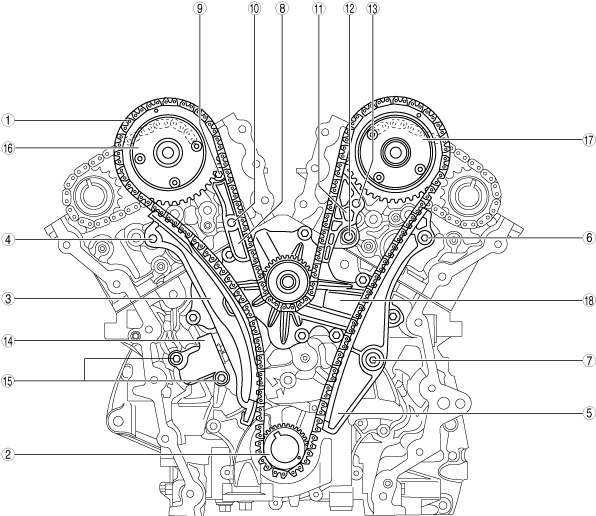
• There are two types of timing chains, a roller chain type and a silent chain type. The parts indicated in the following table differ according to the chain type specification (no interchangeability).
• If the specification for the timing chain is changed, it is necessary to change all parts indicated in the following table at the same time.
Roller chain type
Silent chain type
|
Code
|
Part name
|
Part number
(Roller chain type)
|
Part number
(Silent chain type)
|
|
1
|
Timing chain
|
CY01-12201
CY01-12201-A
|
CA51-12201*1
|
|
2
|
Crankshaft sprocket
|
CY01-11316
|
CA51-11316*1
|
|
3
|
Tensioner arm
|
CY01-12670
|
CA51-12670*1
|
|
4
|
Tensioner arm installation bolt
|
9XG10-729X0
|
9XG15-385X0*1
|
|
5
|
Chain guide
|
CY01-12611
|
CA51-12611*1
|
|
6
|
Chain guide installation bolt No.1
|
9XF03-2797L
|
9XG15-118X0*1
|
|
7
|
Chain guide installation bolt No.2
|
9XG05-743X0
|
9XG14-0947L*1
|
|
8
|
Upper timing chain guide (RH)
|
CY01-12613
|
CA51-12613*1
|
|
9
|
Upper timing chain guide (RH) installation bolt No.1
|
9XF03-2797L
|
9XG15-118X0*1
|
|
10
|
Upper timing chain guide (RH) installation bolt No.2
|
9XF03-2797L
|
9XG15-385X0*1
|
|
11
|
Upper timing chain guide (LH)
|
CY01-12614
|
CA51-12614*1
|
|
12
|
Upper timing chain guide (LH) installation bolt No.1
|
9XF03-2797L
|
9XG15-118X0*1
|
|
13
|
Upper timing chain guide (LH) installation bolt No.2
|
9XF03-2797L
|
9XG15-385X0*1
|
|
14
|
Chain tensioner
|
CY01-12500
CY01-12500-A
|
CA51-12500*1
|
|
15
|
Chain tensioner installation bolt
|
9XF00-300X0
|
9XG15-118X0*1
|
|
16
|
Variable valve timing actuator set (RH)
|
CAY1-12SL0-A
CAY1-12SL0-B
|
CAZ1-12SL0*1
|
|
17
|
Variable valve timing actuator set (LH)
|
CAY2-12SL0-A
CAY2-12SL0-B
|
CAZ2-12SL0*1
|
|
18
|
Water pump
|
CY02-15010-B
CY02-15010-C
|
CA51-15010*1
|
|
-
|
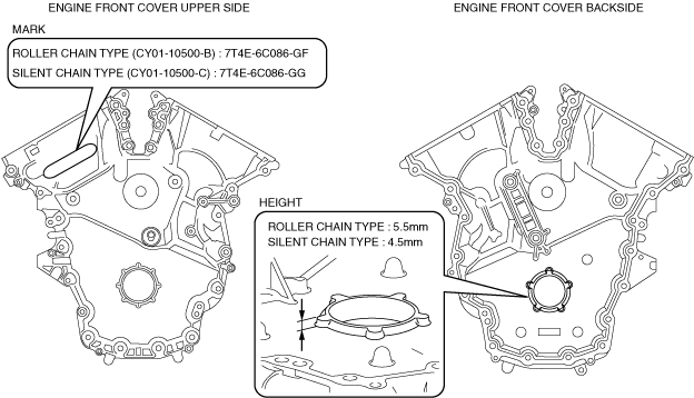
Engine front cover*2
|
CY01-10500-B
|
CY01-10500-C*1
|
*1 :Verify the part numbers referring to the parts catalog because the numbers may change.
*2 :Because the engine front cover can only be changed to the specification for the silent chain, verify the following, identify the specification, and determine whether the replacement is required or not required.
1. Drain the engine oil. (See ENGINE OIL REPLACEMENT [MZI-3.7].)
2. Remove the engine and transaxle component. (See ENGINE REMOVAL/INSTALLATION [MZI-3.7].)
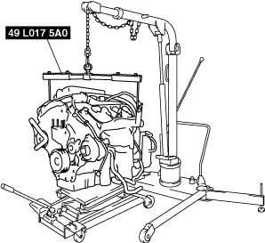
3. Secure the engine and transaxle component using a hoist and the SST.
-
Warning
-
• Protect and stabilize the lowered engine and transaxle component with crossties to prevent injury or damage due to roll over.
4. Remove the dynamic chamber and throttle body as a single unit. (See INTAKE-AIR SYSTEM REMOVAL/INSTALLATION [MZI-3.7].)
5. Remove the ignition coils. (See IGNITION COIL REMOVAL/INSTALLATION [MZI-3.7].)
6. Remove the dipstick.
7. Remove the power steering oil pump drive belt. (See DRIVE BELT REMOVAL/INSTALLATION [MZI-3.7].)
8. Remove the power steering oil pump. (See POWER STEERING OIL PUMP REMOVAL/INSTALLATION [L.H.D.].)(See POWER STEERING OIL PUMP REMOVAL/INSTALLATION [R.H.D.].)
9. Remove the OCV component (LH) (RH). (See TIMING CHAIN REMOVAL/INSTALLATION [MZI-3.7].)
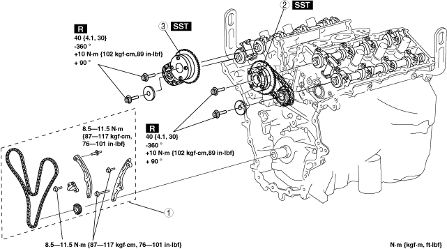
10. Remove in the order indicated in the table.
11. Install in the reverse order of removal.
12. Start the engine and:
- (1) Inspect the runout and contact on the pulley and belt.
-
- (2) Inspect for engine oil, engine coolant, ATF, power steering fluid and fuel leakage.
-
- (3) Verify the ignition timing, idle speed and idle mixture. (See ENGINE TUNE-UP [MZI-3.7].)
-
- (4) Engine accessories operation.
-
13. Perform a road test.
|
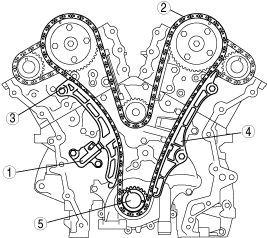
1
|
Timing chain component
|
|
2
|
Variable valve timing actuator component (LH)
|
|
3
|
Variable valve timing actuator component (RH)
|
Timing chain Component Removal Note
-
Caution
-
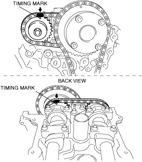
• When removing the timing chain and marking the timing marks on the chain, mark the camshaft timing chain as well.
• Do not rotate the crankshaft counterclockwise. The timing chains may bind, causing engine damage.
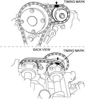
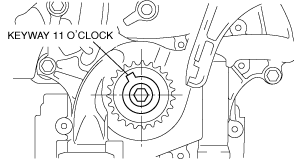
1. Turn the crankshaft clockwise so that the crankshaft keyway is in the 11 o’clock position. (This will position the No.1 cylinder at TDC.)
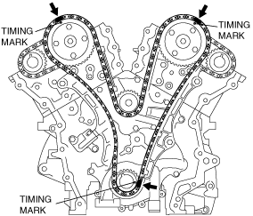
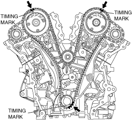
2. Mark the timing chain at the position of each timing sprocket timing mark.
Roller chain type
Silent chain type
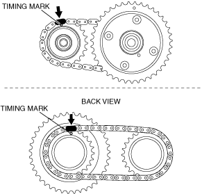
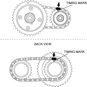
3. Mark the camshaft timing chain at the positions where it is aligned with each of the camshaft sprocket on both banks.
LH
RH
4. Remove the timing chain in the following order.
- (1) Chain tensioner
-
- (2) Timing chain
-
- (3) Tensioner arm
-
- (4) Chain guide
-
- (5) Crankshaft sprocket
-
Variable Valve Timing Actuator Component Removal Note
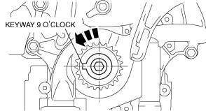
1. Rotate the crankshaft counterclockwise until the keyway is in the 9 o'clock position.
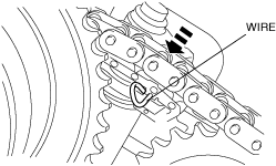
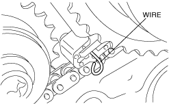
2. Slowly compress the camshaft timing chain tensioner (LH) piston by hand.
3. Insert an approx. 1.0 mm {0.039 in} thin wire or paper clip into the camshaft timing chain tensioner (LH) shown in the figure to hold the tensioner piston.
-
Note
-
• When the timing chain removed, valve spring pressure will rotate the camshaft (LH) approx. 3 ° to a neutral position.
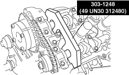
4. Install the SST onto the camshafts (LH).
-
Caution
-
• Always use an appropriate tool (TORX or TORX PLUS). If the appropriate tool is not used, it could result in damage to the bolts or the tools.
-
Tool size
-
TORX: T55
TORX PLUS: 55IP
-
Note
-
• The camshaft sprocket is integrated with the variable valve timing actuator and cannot be disassembled.
5. Remove the variable valve timing actuator, camshaft timing chain and the exhaust camshaft sprocket of the LH bank as a single unit using the appropriate tools.
6. Remove the SST from the camshafts (LH).
7. Slowly compress the camshaft timing chain tensioner (RH) piston by hand.
8. Insert an approx. 1.0 mm {0.039 in} thin wire or paper clip into the camshaft timing chain tensioner (RH) shown in the figure to hold the tensioner piston.
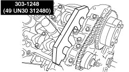
9. Install the SST onto the camshafts (RH).
-
Note
-
• The camshaft sprocket is integrated with the variable valve timing actuator and cannot be disassembled.
10. Remove the variable valve timing actuator, camshaft timing chain and the exhaust camshaft sprocket of the RH bank as a single unit using the appropriate tools.
11. Remove the SST from the camshafts (RH).
Variable Valve Timing Actuator Component Installation Note
1. Align the alignment marks on the camshaft timing chain and both intake and exhaust side camshaft sprockets of both banks.
RH
LH
2. Install the variable valve timing actuator, camshaft timing chain and the exhaust camshaft sprocket of the RH bank as a single unit.
3. Remove the retaining wire inserted into the camshaft timing chain tensioner (RH).
-
Caution
-
• Always use an appropriate tool (TORX or TORX PLUS). If the appropriate tool is not used, it could result in damage to the bolts or the tools.
-
Tool size
-
TORX: T55
TORX PLUS: 55IP
4. Tighten the new camshaft sprocket (RH) installation bolts using the appropriate tools following 4 steps.
- (1) Tighten to 40 N·m {4.1 kgf·m, 30 ft·lbf}.
-
- (2) Loosen 360 ° (one full turn) in reverse order.
-
- (3) Tighten to 10 N·m {102 kgf·cm, 89 in·lbf}.
-
- (4) Tighten to 90 °
-
5. Install the variable valve timing actuator, camshaft timing chain and the exhaust camshaft sprocket of the LH bank as a single unit.
6. Remove the retaining wire inserted into the camshaft timing chain tensioner (LH).
7. Tighten the new camshaft sprocket (LH) installation bolts using the appropriate tools following 4 steps.
- (1) Tighten to 40 N·m {4.1 kgf·m, 30 ft·lbf}.
-
- (2) Loosen 360 ° (one full turn) in reverse order.
-
- (3) Tighten to 10 N·m {102 kgf·cm, 89 in·lbf}.
-
- (4) Tighten to 90 °
-
8. Turn the crankshaft clockwise so that the crankshaft keyway is in the 11 o’clock position. (This will position the No.1 cylinder at TDC.)
9. Follow the “TIMING CHAIN REMOVAL/INSTALLATION” procedure and install the timing chain. (See TIMING CHAIN REMOVAL/INSTALLATION [MZI-3.7].)