 |
ac9wzw00000882
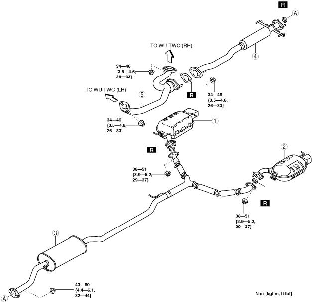
EXHAUST SYSTEM REMOVAL/INSTALLATION [MZI-3.7]
id0115d2800200
1. Disconnect the negative battery cable. (See BATTERY REMOVAL/INSTALLATION [MZI-3.7].)
2. Remove the engine cover. (See ENGINE COVER REMOVAL/INSTALLATION [MZI-3.7].)
3. Remove in the order indicated in the table.
4. Remove the exhaust system insulator. (See Exhaust System Insulator Removal/Installation Note.)
5. Install in the reverse order of removal.
Step 1
ac9wzw00000882
|
|
1
|
Main silencer (RH)
|
|
2
|
Main silencer (LH)
|
|
3
|
Presilencer
|
|
4
|
Middle pipe
|
|
5
|
Front pipe
|
Step 2
ac9wzw00000883
|
|
1
|
WU-TWC bracket (LH)
|
|
2
|
WU-TWC (LH)
|
|
3
|
• Rear HO2S (LH) (PCM connector (2 types))
• HO2S (LH) (PCM connector (3 types))
|
|
4
|
WU-TWC protector No.1 (LH)
|
|
5
|
WU-TWC protector No.2 (LH)
|
|
6
|
WU-TWC hanger bracket No.1 (LH)
|
|
7
|
WU-TWC hanger bracket No.2 (LH)
|
|
8
|
WU-TWC bracket (RH)
|
|
9
|
WU-TWC (RH)
|
|
10
|
• Rear HO2S (RH) (PCM connector (2 types))
• HO2S (RH) (PCM connector (3 types))
|
|
11
|
WU-TWC protector No.1 (RH)
|
|
12
|
WU-TWC protector No.2 (RH)
|
|
13
|
WU-TWC hanger bracket No.1 (RH)
|
|
14
|
WU-TWC hanger bracket No.2 (RH)
|
|
15
|
Exhaust manifold insulator (LH)
|
|
16
|
Exhaust manifold (LH)
|
|
17
|
• Front HO2S (LH) (PCM connector (2 types))
• A/F sensor (LH) (PCM connector (3 types))
|
|
18
|
Stud
|
|
19
|
• Front HO2S (RH) (PCM connector (2 types))
• A/F sensor (RH) (PCM connector (3 types))
|
|
20
|
Exhaust manifold insulator (RH)
|
|
21
|
Exhaust manifold (RH)
|
|
22
|
Stud
|
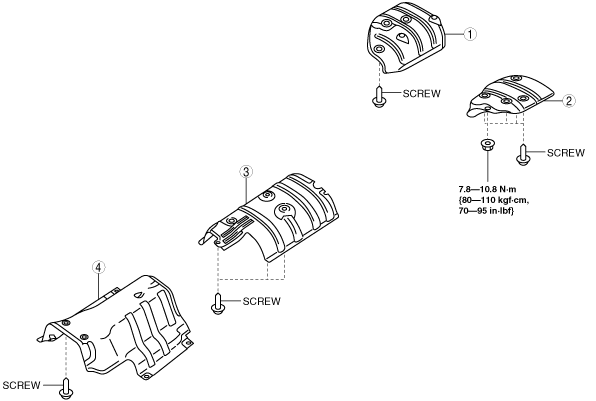
Exhaust System Insulator Removal/Installation Note
1. Remove the exhaust system insulator in the order shown in the figure.
2. Install in the reverse order of removal.
ac9wzw00000884
|
|
1
|
Main silencer insulator (RH)
|
|
2
|
Main silencer insulator (LH)
|
|
3
|
Presilencer insulator
|
|
4
|
Middle pipe insulator
|
Warm Up Three Way Catalytic Converter (WU-TWC) (RH) Removal Note
2WD
1. Remove the joint shaft. (See JOINT SHAFT REMOVAL/INSTALLATION [2WD].)
2. Remove the WU-TWC (RH).
4WD
1. Remove the joint shaft. (See JOINT SHAFT REMOVAL/INSTALLATION [4WD].)
2. Remove the insulator. (See STEERING GEAR AND LINKAGE REMOVAL/INSTALLATION [L.H.D.].)(See STEERING GEAR AND LINKAGE REMOVAL/INSTALLATION [R.H.D.].)
3. Remove the No.1 engine mount (transaxle side). (See ENGINE REMOVAL/INSTALLATION [MZI-3.7].)
4. Push up the engine.
5. Remove the WU-TWC (RH).
Exhaust Manifold Insulator (LH) Removal Note
1. Set the fan control module out of the way. (See COOLING FAN COMPONENT REMOVAL/INSTALLATION [MZI-3.7].)
2. Remove the exhaust manifold Insulator (LH).
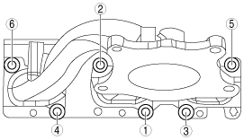
Exhaust Manifold (RH) Installation Note
1. Tighten the exhaust manifold (RH) installation nuts in the order shown in the figure.
ac9wzw00002094
|
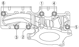
Exhaust Manifold (LH) Installation Note
1. Tighten the exhaust manifold (RH) installation nuts in the order shown in the figure.
ac9wzw00002095
|
Warm Up Three Way Catalytic Converter (WU-TWC) (RH) Installation Note
1. Tighten nut of D with tightening torque.
2. Temporarily tighten bolt of E.
3. Temporarily tighten nut of F.
4. Temporarily tighten bolt of G.
5. Tighten nut of F with tightening torque.
6. Tighten bolt of G with tightening torque.
7. Tighten bolt of E with tightening torque.
Warm Up Three Way Catalytic Converter (WU-TWC) (LH) Installation Note
1. Temporarily tighten bolt of A.
2. Temporarily tighten nut of B.
3. Temporarily tighten bolt of C.
4. Tighten nut of B with tightening torque.
5. Tighten bolt of C with tightening torque.
6. Tighten bolt of A with tightening torque.