 |
ac9uuw00001931
REAR UPPER ARM REMOVAL/INSTALLATION [4WD]
id0214008008a2
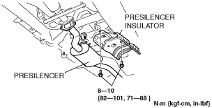
1. Remove the presilencer. (See EXHAUST SYSTEM REMOVAL/INSTALLATION [MZI-3.7].)
2. Remove the presilencer insulator.
ac9uuw00001931
|
3. Remove the propeller shaft. (See PROPELLER SHAFT REMOVAL/INSTALLATION.)
4. Remove the rear ABS wheel-speed sensor. (See REAR ABS WHEEL-SPEED SENSOR REMOVAL/INSTALLATION [4WD].)
5. Disconnect the rear auto leveling sensor connector. (Vehicle with headlight auto leveling system) (See REAR AUTO LEVELING SENSOR REMOVAL/INSTALLATION.)
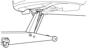
6. Support the jack up point for the front crossmember using a garage jack.
ampjjw00000887
|
7. Jack up the rear suspension with unloaded condition.
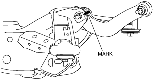
8. Mark the rear upper arm and rear crossmember shown in the figure.
am8rrw00001829
|
9. Remove the rear coil spring. (See REAR COIL SPRING REMOVAL/INSTALLATION.)
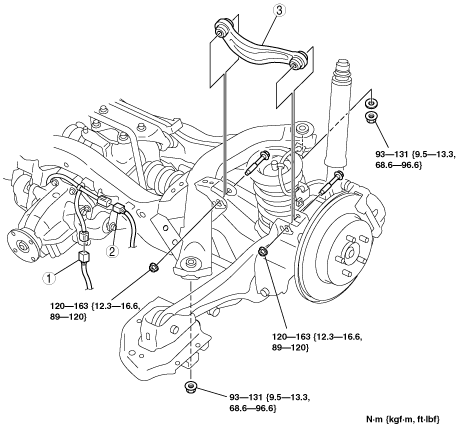
10. Remove in the order indicated in the table.
11. Install in the reverse order of removal.
12. Inspect for rear wheel alignment, and adjust it as necessary. (See REAR WHEEL ALIGNMENT [4WD].)
ac9uuw00002075
|
|
1
|
Differential oil temperature sensor connector
|
|
2
|
4WD solenoid connector
|
|
3
|
Rear upper arm
(See Rear upper arm Removal Note.)
|
Rear upper arm Removal Note
1. Remove the rear lateral link installation bolts.
2. Loosen the rear upper arm installation bolts.
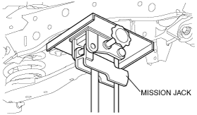
3. Support the rear crossmember and differential component using a mission jack.
am8rrw00001445
|
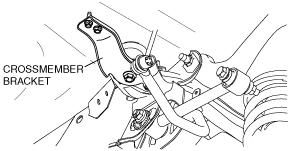
4. Remove the crossmember bracket.
am8rrw00001446
|
5. Loosen the rear crossmember installation nut, and lower the crossmember approx. 50 mm {2.0 in}.
6. Remove the rear upper arm.
Rear upper arm Installation Note
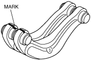
1. Place the new rear upper arm together with the removed rear upper arm and place an alignment mark on the new rear upper arm.
am8rrw00001830
|
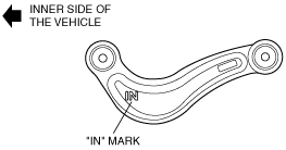
2. Point the 'IN' mark towards the inside of the vehicle, align the rear upper arm and rear crossmember alignment marks, and install the rear upper arm.
ac9uuw00000932
|
3. Tighten the rear upper arm inner side bolt.
4. Install the rear crossmember component.