 |
ac9wzw00000816
WHEEL HUB COMPONENT REMOVAL/INSTALLATION [4WD]
id0312008004a2
1. Remove the rear ABS wheel-speed sensor. (See REAR ABS WHEEL-SPEED SENSOR REMOVAL/INSTALLATION [4WD].)
2. Remove the rear lateral link. (See REAR LATERAL LINK REMOVAL/INSTALLATION.)
3. Remove the rear coil spring. (See REAR COIL SPRING REMOVAL/INSTALLATION.)
4. Remove the rear lower arm. (See REAR LOWER ARM REMOVAL/INSTALLATION.)
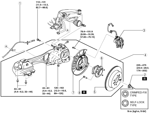
5. Remove in the order indicated in the table.
6. Install in the reverse order of removal.
7. Inspect for rear wheel alignment, and adjust it as necessary. (See REAR WHEEL ALIGNMENT [4WD].)
ac9wzw00000816
|
|
1
|
Rear parking brake cable
|
|
2
|
Locknut (crimped-fix type)/Locknut (self-lock type)
|
|
3
|
Brake caliper component
|
|
4
|
Rear trailing link and rear wheel hub component
|
|
5
|
Disc plate
|
|
6
|
Wheel hub component
|
|
7
|
Parking brake shoe component
|
|
8
|
Wheel hub bolt
|
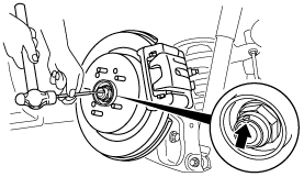
Locknut (Crimped-fix Type) Removal Note
1. Knock the crimped portion of the locknut outward using a small chisel and a hummer.
ampjjw00004289
|
2. Lock the hub by applying the brakes.
3. Remove the locknut.
Rear Trailing Link and Rear Wheel Hub Component Removal Note
1. Support the rear trailing link and rear wheel hub component using a jack.
ac9uuw00001244
|
2. Separate the rear drive shaft (rear axle side) from the wheel hub.
3. Remove the trailing link and rear wheel hub component.
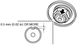
Locknut (Crimped-fix Type) Installation Note
1. Install a new locknut and stake it as shown.
ac9wzw00001370
|