 |
ac9wzw00001137
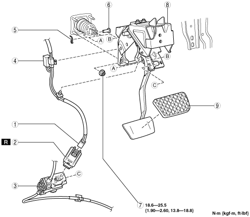
BRAKE PEDAL REMOVAL/INSTALLATION [L.H.D.]
id041100801250
1. Remove in the order indicated in the table.
2. Install in the reverse order of removal.
ac9wzw00001137
|
|
1
|
Brake switch connector
|
|
2
|
Brake switch
|
|
3
|
Interlock cable
(See INTERLOCK CABLE ADJUSTMENT.)
|
|
4
|
Noise filter
|
|
5
|
Snap pin
|
|
6
|
Clevis pin
|
|
7
|
Nut
|
|
8
|
Brake pedal
(See Brake Pedal Removal Note.)
|
|
9
|
Pedal pad
|
Brake Pedal Removal Note
1. Remove the windshield wiper arm and blade. (See WINDSHIELD WIPER ARM AND BLADE REMOVAL/INSTALLATION.)
2. Remove the cowl grille. (See COWL GRILLE REMOVAL/INSTALLATION.)
3. Remove the windshield wiper motor. (See WINDSHIELD WIPER MOTOR REMOVAL/INSTALLATION.)
4. Remove the cowl panel. (See COWL PANEL REMOVAL/INSTALLATION.)
5. Remove the decoration panel. (See DECORATION PANEL REMOVAL/INSTALLATION.)
6. Remove the front console box mat. (See FRONT CONSOLE BOX MAT REMOVAL/INSTALLATION.)
7. Remove the indicator panel. (See INDICATOR PANEL REMOVAL/INSTALLATION.)
8. Remove the front console box. (See FRONT CONSOLE BOX REMOVAL/INSTALLATION.)
9. Remove the dashboard under cover. (See DASHBOARD UNDER COVER REMOVAL/INSTALLATION.)
10. Remove the side wall. (See SIDE WALL REMOVAL/INSTALLATION.)
11. Remove the console panel. (See CONSOLE PANEL REMOVAL/INSTALLATION.)
12. Remove the console cover. (See CONSOLE COVER REMOVAL/INSTALLATION.)
13. Remove the console. (See CONSOLE REMOVAL/INSTALLATION.)
14. Remove the front scuff plate inner. (See FRONT SCUFF PLATE REMOVAL/INSTALLATION.)
15. Remove the front side trim. (See FRONT SIDE TRIM REMOVAL/INSTALLATION.)
16. Remove the bonnet release lever. (See BONNET LATCH AND RELEASE LEVER REMOVAL/INSTALLATION.)
17. Remove the lower panel. (See LOWER PANEL REMOVAL/INSTALLATION.)
18. Remove the glove compartment. (See GLOVE COMPARTMENT REMOVAL/INSTALLATION.)
19. Remove the A-pillar trim. (See A-PILLAR TRIM REMOVAL/INSTALLATION.)
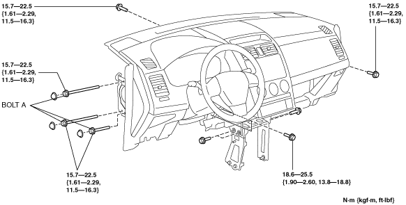
20. Remove the dashboard installation bolts as shown in the figure.
ac9wzw00001138
|
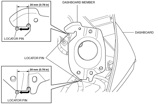
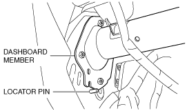
21. Lift the dashboard upward and move it 20 mm {0.78 in} to the rear of the vehicle after the locator pin for the dashboard member is in the position shown in the figure.
ac9wzw00001139
|
ac9wzw00001140
|
22. Move the power brake unit to the vehicle front where the power brake unit fork does not interfere with the brake pedal arm.
23. Remove the brake pedal.
Brake Switch Installation Note
1. Inspect the brake pedal. (See BRAKE PEDAL INSPECTION [L.H.D.].)
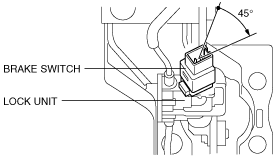
2. With the brake pedal fully released, insert a new brake switch into the installation hole on the lock unit.
3. Secure the brake switch by turning it clockwise 45°.
ac9wzw00001141
|
Brake Switch Connector Installation Note
1. Inspect the brake pedal. (See BRAKE PEDAL INSPECTION [L.H.D.].)
2. With the brake pedal in its original position, install the brake switch to the brake switch connector.