AUTOMATIC TRANSAXLE FLUID (ATF) LEVEL ADJUSTMENT [AY6A-EL, AY6AX-EL]
id0517k3297300
-
Caution
-
• Adjust the ATF level when the ATF is at the appropriate temperature (between 37 °C {99 °F} and under 47 °C {117 °F}).
• For a low amount of ATF flowing from the overflow tube, the fluid level is not adjusted to the specification because the fluid that has accumulated in the overflow tube is what has flowed from the overflow tube.
• Do not remove the blind cap because it is not a removable part.
• Perform the following procedure for the ATF level adjustment.
-
ATF Replenishment
1. Remove the fresh-air duct and air cleaner installation bolts and slide the fresh-air duct and air cleaner as a single unit to the vehicle front. (See INTAKE-AIR SYSTEM REMOVAL/INSTALLATION [MZI-3.7].)
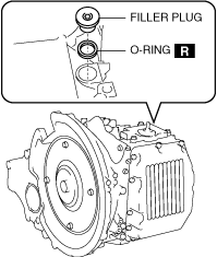
2. Remove the filler plug and the O-ring.
3. Add ATF from the filler plug hole.
-
ATF capacity (approx. quantity)
-
6.6 L {7.0 US qt, 5.8 Imp qt}
-
ATF replenishment amount
-
• Replacing the oil hose: 0.3 L {0.3 US qt, 0.3 Imp qt}
-
• Replacing the torque converter: 2.6 L {2.7 US qt, 2.3 Imp qt}
-
• Replacing the drain plug, oil pipe component (transaxle side), control valve body cover and control valve body: 6.1 L {6.4 US qt, 5.4 Imp qt}
-
• Disassembling/assembling the transaxle: 6.1 L {6.4 US qt, 5.4 Imp qt}
4. Temporarily tighten the filler plug reusing the O-ring.
5. Go to “ATF Level Adjustment”. (See ATF Level Adjustment.)
ATF Level Adjustment
-
Caution
-
• Adjust the ATF level when the ATF is at the appropriate temperature (between 37 °C {99 °F} and under 47 °C {117 °F}).
-
Note
-
• Be careful of perform the following when performing “ATF Level Adjustment”.
-
― Do not stop the engine.
― Do not drive the vehicle.
― Position the vehicle on level ground.
Using M-MDS
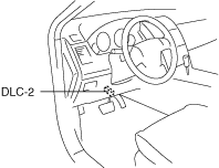
1. Connect the M-MDS to the DLC-2.
2. Verify the ATF temperature using the PID/DATA monitor function “TFT”. (See ON-BOARD DIAGNOSTIC SYSTEM DTC INSPECTION [AY6A-EL, AY6AX-EL].).
-
• High temperature (47 °C {117 °F} or more)
• Appropriate temperature (between 37 °C {99 °F} and under 47 °C {117 °F})
• Low temperature (less than 37 °C {99 °F})
3. Start the engine.
4. Warm up the engine while idling it until the ATF temperature reaches the lower limit of 37 °C {99 °F}.
5. Perform the following procedure.
-
Note
-
• Perform the following procedure immediately because the ATF temperature will exceed the appropriate temperature (between 37 °C {99 °F} and under 47 °C {117 °F}).
• Shift the selector lever to each positions and hold for 2 s or more.
- (1) Shift the selector lever to the P position.
-
- (2) Shift the selector lever in the order of P position→R position→N position→D position.
-
- (3) Shift the selector lever in the order of D position→N position→R position→P position.
-
- (4) Shift the selector lever in the order of P position→R position→N position→D position.
-
- (5) Shift the selector lever in the order of D position→N position→R position→P position.
-
6. Verify that the ATF temperature is within the appropriate temperature range (between 37 °C {99 °F} and under 47 °C {117 °F}).
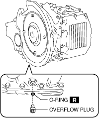
7. Remove the overflow plug and the O-ring while leaving the engine idling.
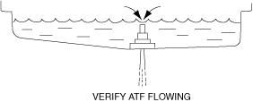
8. Verify that ATF flows from the overflow tube.
-
Caution
-
• For a low amount of ATF flowing from the overflow tube, the fluid level is not adjusted to the specification because the fluid that has accumulated in the overflow tube is what has flowed from the overflow tube.
-
Note
-
• If there is no ATF flowing from the overflow tube, fill with ATF from the filler plug hole until ATF flows from the overflow tube.
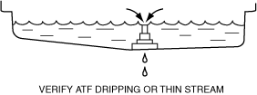
9. Allow the ATF to drain from the overflow tube until it drips or becomes a thin stream.
10. Apply ATF to a new O-ring and install it on the overflow plug.
11. Install a new O-ring and overflow plug.
-
Tightening torque
-
5.9—8.8 N·m {61—89 kgf·cm, 53—77 in·lbf}
12. Wipe off ATF remaining on the overflow plug.
13. Stop the engine.
14. Install a new O-ring and filler plug.
-
Tightening torque
-
24—54 N·m {2.5—5.5 kgf·m, 18—39 ft·lbf}
15. Install the fresh-air duct and air cleaner component as a single unit. (See INTAKE-AIR SYSTEM REMOVAL/INSTALLATION [MZI-3.7].)
16. Connect the negative battery cable.
Using ATF temperature display mode
-
Note
-
• Perform the procedure for switching to the ATF temperature display mode within 3 min. If the procedure is not completed within 3 min, the switching procedure is cancelled.
• If the flashing of each light cannot be verified as according to the procedure while switching to the ATF temperature display mode, the switching procedure has failed. Repeat the procedure from the beginning.
1. Engage the parking brake and use wheel chocks at the front and rear of the wheels.
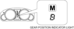
2. Perform the following and verify that the gear position indicator light flashes 2 times.
- (1) Switch the ignition to ACC.
-
- (2) Turn the A/C switch off.
-
- (3) Depress the brake pedal with the left foot and hold it in that condition (continue to depress the brake pedal until Step 5 is completed).
-
- (4) Shift the selector lever from the P position to the M position.
-
- (5) Depress the accelerator pedal with the right foot all the way down and hold it in that condition (continue to depress the brake pedal until Step 4 (3) is completed).
-
- (6) Shift the selector lever to the M (+) or M (-) and hold it in that condition.
-
- (7) Switch the ignition ON (engine off).
-
- (8) Verify that the gear position indicator light flashes 2 times after approx. 5 s.
-
3. Perform the following procedure and verify that the N position display of the selector indicator light flashes 2 times.
-
Note
-
• Slowly and firmly shift the selector lever operation.
- (1) Shift the selector lever in the order of M position→D position→N position→R position→P position.
-
- (2) Shift the selector lever in the order of P position→R position→N position.
-
- (3) Remove the right foot from the accelerator pedal.
-
- (4) Verify that the N position display flashes 2 times.
-
4. Perform the following procedure and verify that the AT warning light flashes 2 times.
- (1) Start the engine.
-
- (2) Shift the selector lever quickly between the N position and the D position for 6 s or more.
-
- (3) Verify that the AT warning light flashes 2 times.
-
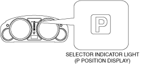
5. Perform the following procedure and verify that the P position display flashes.
-
Note
-
• Shift the selector lever to each positions and hold for 2 s or more.
- (1) Shift the selector lever to the P position.
-
- (2) Shift the selector lever in the order of P position→R position→N position→D position.
-
- (3) Shift the selector lever in the order of D position→N position→R position→P position.
-
- (4) Shift the selector lever in the order of P position→R position→N position→D position.
-
- (5) Shift the selector lever in the order of D position→N position→R position→P position.
-
- (6) Verify that the TCM switches to the ATF temperature display mode via the P position display flashing.
-
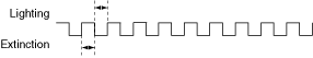
6. Verify the ATF temperature using the P position display flashing pattern.
-
Note
-
• Finish the "ATF temperature display mode" when any one of the following conditions is met:
-
― Switch the ignition to ACC or off
― Vehicle speed is 3 km/h {2 mph} or more
― Malfunction occurs in transaxle
|
ATF temperature
|
Selector indicator light (P position display) flashing pattern
|
|
High temperature (47 °C {117 °F} or more)
|
 |
|
Appropriate temperature (between 37 °C {99 °F} and under 47 °C {117 °F})
|
 |
|
Low temperature (less than 37 °C {99 °F})
|
 |
 |
 |
 |
7. Verify that the ATF temperature is within the appropriate temperature range (between 37 °C {99 °F} and under 47 °C {117 °F}).
8. Remove the overflow plug and the O-ring while leaving the engine idling.
9. Verify that ATF flows from the overflow tube.
-
Caution
-
• For a low amount of ATF flowing from the overflow tube, the fluid level is not adjusted to the specification because the fluid that has accumulated in the overflow tube is what has flowed from the overflow tube.
-
Note
-
• If there is no ATF flowing from the overflow tube, fill with ATF from the filler plug hole until ATF flows from the overflow tube.
10. Allow the ATF to drain from the overflow tube until it drips or becomes a thin stream.
11. Apply ATF to a new O-ring and install it on the overflow plug.
12. Install a new O-ring and overflow plug.
-
Tightening torque
-
5.9—8.8 N·m {61—89 kgf·cm, 53—77 in·lbf}
13. Wipe off ATF remaining on the overflow plug.
14. Stop the engine.
15. Install a new O-ring and filler plug.
-
Tightening torque
-
24—54 N·m {2.5—5.5 kgf·m, 18—39 ft·lbf}
16. Install the fresh-air duct and air cleaner component as a single unit. (See INTAKE-AIR SYSTEM REMOVAL/INSTALLATION [MZI-3.7].)
17. Connect the negative battery cable.