 |
ac9wzw00000718
DIAGNOSTIC TROUBLE CODE NUMBER INSPECTION
id070200802000
1. Remove the following parts: (R.H.D.)
2. Remove the following parts: (L.H.D.)
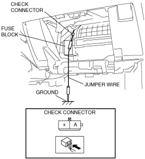
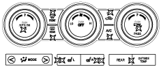
3. Short the check connector terminal A to the ground using a jumper wire.
R.H.D.
ac9wzw00000718
|
L.H.D.
ac9uuw00001151
|
4. Expose the solar radiation sensor to natural sunlight.
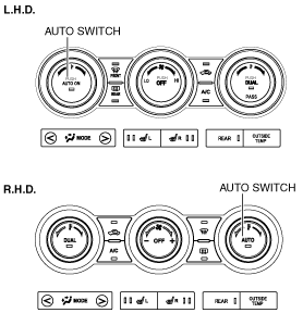
5. Turn the ignition switch to ON position.
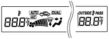
6. Read DTCs on the information display. Carry out DTC inspection. (present and past failure indication modes)
7. After completion of repairs, erase all diagnostic trouble code(s) from memory. (See Erasing Past Failure Memory.)
8. Remove the jumper wire.
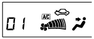
Present Failure Indication Mode
Past Failure Indication Mode
ac9wzw00001526
|
Erasing Past Failure Memory
ac9wzw00001527
|
DTC Table
|
No. |
Output pattern |
Malfunction location |
Detected condition |
Memory function |
Page |
|---|---|---|---|---|---|
|
02
|
 |
Solar radiation sensor (present malfunction)
|
Solar radiation sensor (RH) circuit short
|
—
|
(See DTC 02.)
|
|
04
|
 |
Solar radiation sensor (LH) circuit short
|
—
|
(See DTC 04.)
|
|
|
06
|
 |
Cabin temperature sensor (present malfunction)
|
Cabin temperature sensor circuit open/short circuit
|
—
|
(See DTC 06.)
|
|
07
|
 |
Cabin temperature sensor (past malfunction)
|
When an open/short has occurred in the cabin temperature sensor circuit 1 time or more in the past
|
X
|
(See DTC 07.)
|
|
10
|
 |
Front evaporator temperature sensor (present malfunction)
|
Front evaporator temperature sensor circuit open/short circuit
|
—
|
(See DTC 10.)
|
|
11
|
 |
Front evaporator temperature sensor (past malfunction)
|
When an open/short has occurred in the front evaporator temperature sensor circuit 1 time or more in the past
|
X
|
(See DTC 11.)
|
|
12
|
 |
Ambient temperature sensor (present malfunction)
|
Ambient temperature sensor circuit open/short circuit
|
—
|
(See DTC 12.)
|
|
13
|
 |
Ambient temperature sensor (past malfunction)
|
When an open/short has occurred in the ambient temperature sensor circuit 1 time or more in the past
|
X
|
(See DTC 13.)
|
|
18
|
 |
Driver-side front air mix actuator (potentiometer) (present malfunction)*1
Passenger-side front air mix actuator (potentiometer) (present malfunction)*2
|
Driver-side front air mix actuator (potentiometer) circuit open/short circuit*1
Passenger-side front air mix actuator (potentiometer) circuit open/short circuit*2
|
—
|
(See DTC 18.)
|
|
19
|
 |
Driver-side front air mix actuator (potentiometer) (past malfunction)*1
Passenger-side front air mix actuator (potentiometer) (past malfunction)*2
|
When an open/short has occurred in the driver-side front air mix actuator (potentiometer) circuit 1 time or more in the past*1
When an open/short has occurred in the passenger-side front air mix actuator (potentiometer) circuit 1 time or more in the past*2
|
X
|
(See DTC 19.)
|
|
21
|
 |
Front airflow mode actuator (potentiometer) (present malfunction)
|
Front airflow mode actuator (potentiometer) circuit open/short circuit
|
—
|
(See DTC 21.)
|
|
22
|
 |
Front airflow mode actuator (potentiometer) (past malfunction)
|
When an open/short has occurred in the front airflow mode actuator (potentiometer) circuit 1 time or more in the past
|
X
|
(See DTC 22.)
|
|
37
|
 |
Passenger-side front air mix actuator (potentiometer) (present malfunction)*1
Driver-side front air mix actuator (potentiometer) (present malfunction)*2
|
Passenger- side front air mix actuator (potentiometer) circuit open/short circuit*1
Driver-side front air mix actuator (potentiometer) circuit open/short circuit*2
|
—
|
(See DTC 37.)
|
|
38
|
 |
Passenger-side front air mix actuator (potentiometer) (past malfunction)*1
Driver-side front air mix actuator (potentiometer) (past malfunction)*2
|
When an open/short has occurred in the passenger-side front air mix actuator (potentiometer) circuit 1 time or more in the past*1
When an open/short has occurred in the driver-side front air mix actuator (potentiometer) circuit 1 time or more in the past*2
|
X
|
(See DTC 38.)
|
|
58
|
 |
Driver-side front air mix actuator (motor lock) (past malfunction)*1
Passenger-side front air mix actuator (motor lock) (past malfunction)*2
|
When motor lock has occurred in the driver-side front air mix actuator circuit 1 time or more in the past*1
When motor lock has occurred in the passenger-side front air mix actuator circuit 1 time or more in the past*2
|
X
|
(See DTC 58.)
|
|
59
|
 |
Front airflow mode actuator (motor lock) (past malfunction)
|
When motor lock has occurred in the front airflow mode actuator circuit 1 time or more in the past
|
X
|
(See DTC 59.)
|
|
61
|
 |
Passenger-side front air mix actuator (motor lock) (past malfunction)*1
Driver-side front air mix actuator (motor lock) (past malfunction)*2
|
When motor lock has occurred in the passenger-side front air mix actuator circuit 1 time or more in the past*1
When motor lock has occurred in the driver-side front air mix actuator circuit 1 time or more in the past*2
|
X
|
(See DTC 61.)
|
|
68
|
 |
Rear climate control unit communication system (past malfunction)
|
When an open/short has occurred in the between front climate control unit and rear climate control unit communication circuit 1 time or more in the past
|
-
|
(See DTC 68.)
|
|
69
|
 |
Rear climate control unit communication system (present malfunction)
|
Between front climate control unit and rear climate control unit communication circuit open/short circuit
|
-
|
(See DTC 69.)
|
|
76
|
 |
Rear air mix actuator (potentiometer) (present malfunction)
|
Rear air mix actuator (potentiometer) circuit open/short circuit
|
—
|
(See DTC 76.)
|
|
77
|
 |
Rear air mix actuator (potentiometer) (past malfunction)
|
When an open/short has occurred in the rear air mix actuator (potentiometer) circuit 1 time or more in the past
|
X
|
(See DTC 77.)
|
|
78
|
 |
Rear evaporator temperature sensor (present malfunction)
|
Rear evaporator temperature sensor circuit open/short circuit
|
—
|
(See DTC 78.)
|
|
79
|
 |
Rear evaporator temperature sensor (past malfunction)
|
When an open/short has occurred in the rear evaporator temperature sensor circuit 1 time or more in the past
|
X
|
(See DTC 79.)
|
|
85
|
 |
Rear airflow mode actuator (potentiometer) (present malfunction)
|
Rear airflow mode actuator (potentiometer) circuit open/short circuit
|
—
|
(See DTC 85.)
|
|
86
|
 |
Rear airflow mode actuator (potentiometer) (past malfunction)
|
When an open/short has occurred in the rear airflow mode actuator (potentiometer) circuit 1 time or more in the past
|
X
|
(See DTC 86.)
|
|
95
|
 |
Rear air mix actuator (motor lock) (past malfunction)
|
When motor lock has occurred in the rear air mix actuator circuit 1 time or more in the past
|
X
|
(See DTC 95.)
|
|
96
|
 |
Rear airflow mode actuator (motor lock) (past malfunction)
|
When motor lock has occurred in the rear airflow mode actuator circuit 1 time or more in the past
|
X
|
(See DTC 96.)
|
Output Device Operation Check Mode
Inspection
1. Warm up the engine.
2. Turn the ignition switch to LOCK position.
3. Remove the following parts: (R.H.D.)
4. Remove the following parts: (L.H.D.)
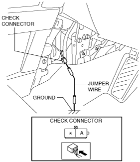
5. Short the check connector terminal A to the ground using a jumper wire.
R.H.D.
ac9wzw00000718
|
L.H.D.
ac9uuw00001151
|
6. Expose the solar radiation sensor to natural sunlight.
7. Start the engine.
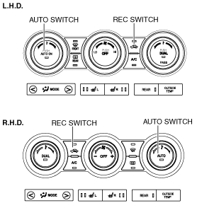
8. Press the AUTO switch.
ac9wzw00001527
|
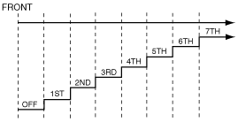
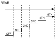
9. Verify the operation of the each output device when changing steps by pressing the REC switch, and referring to the output device operation check chart.
10. Turn the ignition switch to LOCK position to end the output device operation check mode.
Output device operation check table
|
Step |
Operating device |
Operating conditions |
Monitor* |
Output to information display |
|---|---|---|---|---|
|
1
|
Front climate control unit
|
 |
Entire illumination of climate control display
|
• Entire illumination of climate control display
|
|
Information display
|
 |
|||
|
2
|
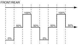
Blower motor speed
|
 |
01
|
• The front A/C airflow volume is displayed in the front airflow volume display area.
|
 |
 |
|||
|
3
|
Air mix actuator operation
|
 |
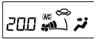
21.0 (100%)
|
• The display is the same as the set temperature display
|
|
20.5 (50%)
|
 |
|||
|
20.0 (0%)
|
||||
|
4
|
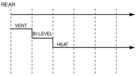
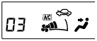
Airflow mode actuator operation
|
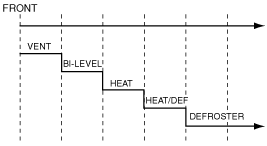 |
03
|
• The front A/C airflow mode is displayed in the front mode display area.
• The rear A/C airflow mode cannot be displayed.
|
 |
 |
|||
|
5
|
Air intake actuator operation
|
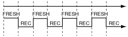 |
04
|
• The intake mode is displayed in the intake mode display area.
• "A/C" is displayed when the A/C is on.The A/C switch indicator illuminates during A/C ON.
|
|
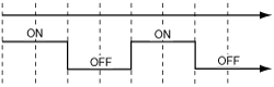
A/C compressor operation
|
 |
 |