|
1
|
VERIFY FREEZE FRAME DATA HAS BEEN RECORDED
• Has FREEZE FRAME DATA been recorded?
|
Yes
|
Go to the next step.
|
|
No
|
Record FREEZE FRAME DATA on the repair order, then go to the next step.
|
|
2
|
VERIFY RELATED SERVICE INFORMATION AVAILABILITY
• Verify related Service Information availability.
• Is any related Service Information available?
|
Yes
|
Perform repair or diagnosis according to the available Service Information.
• If the vehicle is not repaired, go to the next step.
|
|
No
|
Go to the next step.
|
|
3
|
INSPECT THROTTLE POSITION OPEN CIRCUIT AND CLOSED VOLTAGES
• Turn the ignition switch to the ON position (Engine off).
• Access the PCM and monitor the TP1 and TP2 PIDs.
• Verify the following values of the PIDs when depressing the accelerator pedal to the floor and releasing.
-
― Pedal fully released: TP1 is 3.7—4.7 V
― Pedal fully released: TP2 is 0.3—1.9 V
― Pedal fully depressed: TP1 is 0.7—2.9 V
― Pedal fully depressed: TP2 is 4.1—4.7 V
• Are both PIDs within the specification?
|
Yes
|
Go to the Step 5.
|
|
No
|
Go to the next step.
|
|
4
|
INSPECT FOR OBSTRUCTION OF THROTTLE BODY
-
Warning
-
• Substantial opening and closing torque is applied by this system. To prevent injury, be careful to keep fingers away from throttle mechanism when actuated. Failure to follow these instructions may result in personal injury.
• Turn the ignition switch off.
• Remove the air hose from the throttle body.
• Visually inspect for throttle plate obstructions or sludge.
• Slowly, push the throttle plate to wide open and release.
• Does the throttle plate move freely to wide open and back?
|
Yes
|
Go to the Step 7.
|
|
No
|
Isolate and repair the obstruction. Then go to Step 9.
|
|
5
|
INSPECT TP SENSOR OPERATION
• Turn the ignition switch to the ON position (Engine off).
• Access the PCM and monitor the TP1 and TP2 PIDs.
• Slowly press the accelerator pedal from fully released to fully depressed while observing the voltage readings.
• Use the chart as a reference.
• Do all signal values smoothly change when the accelerator is depressed?
|
Yes
|
Go to the next step.
|
|
No
|
Replace the throttle body. Then go to Step 9.
|
|
6
|
INSPECT TP SENSOR CIRCUIT FOR INTERMITTENT CONCERN
• Access the PCM and monitor the TP1 and TP2 PIDs.
• Wiggle, shake, and bend the wiring harness from the TP to the PCM.
• Are the voltages between 0.49—4.65 V?
|
Yes
|
Go to the next step.
|
|
No
|
Repair or replace suspected part, then go to Step 9.
|
|
7
|
INSPECT THROTTLE ACTUATOR CONTROL MOTOR VISUALLY
-
Note
-
• Make sure the throttle body connector is properly connected.
• Turn the ignition switch off.
• Inspect the throttle actuator control motor for damaged housing, wiring harness connector, and wiring harness.
• Are there any concerns with the throttle actuator control motor hardware?
|
Yes
|
Replace the throttle body. Then go to Step 9.
|
|
No
|
Go to the next step.
|
|
8
|
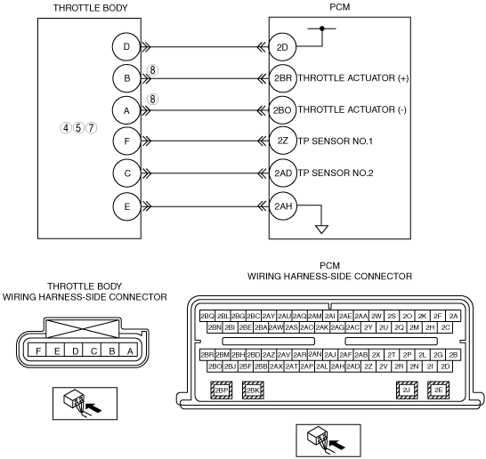
INSPECT THROTTLE ACTUATOR CONTROL CIRCUITS FOR SHORT EACH OTHER
• Turn the ignition switch off.
• Disconnect the throttle body and PCM connector.
• Measure resistance between throttle actuator terminal A and B.
• Is the resistance more than 10 kilohms?
|
Yes
|
Go to the next step.
|
|
No
|
Repair or replace suspected part, then go to the next step.
|
|
9
|
VERIFY TROUBLESHOOTING OF DTC P2111 HAS BEEN COMPLETED
• Verify that all disconnected connectors reconnected.
• Clear the DTC from the PCM memory using the M-MDS.
• Perform the “KOEO or KOER self-test” using the M‐MDS.
• Is the PENDING CODE for the DTC present?
|
Yes
|
Replace the PCM, then go to the next step.
|
|
No
|
Go to the next step.
|
|
10
|
VERIFY AFTER REPAIR PROCEDURE
• Perform the “AFTER REPAIR PROCEDURE”.
• Are any DTCs present?
|
Yes
|
Go to the applicable DTC inspection.
|
|
No
|
Troubleshooting completed.
|