|
1
|
VERIFY FREEZE FRAME DATA HAS BEEN RECORDED
• Has FREEZE FRAME DATA been recorded?
|
Yes
|
Go to the next step.
|
|
No
|
Record FREEZE FRAME DATA on the repair order, then go to the next step.
|
|
2
|
VERIFY RELATED SERVICE INFORMATION AVAILABILITY
• Verify related Service Information availability.
• Is any related Service Information available?
|
Yes
|
Perform repair or diagnosis according to the available Service Information.
• If the vehicle is not repaired, go to the next step.
|
|
No
|
Go to the next step.
|
|
3
|
INSPECT ACCELERATOR PEDAL FOR OBSTRUCTION
• Turn the ignition switch to the ON position (Engine off).
• Depress the accelerator pedal fully to the floor and release.
• Does the pedal move freely to the floor and back?
|
Yes
|
Go to the next step.
|
|
No
|
Isolate and repair the obstruction.Then go to Step 12.
|
|
4
|
INSPECT APP SENSOR SIGNAL VOLTAGE RANGES FOR ACCELERATOR PEDAL FULLY APPLIED AND DEPRESS POSITIONS
• Access the PCM and monitor the APP1, APP2 and APP3 PIDs.
• Verify the following values of the PIDs when depressing the accelerator pedal fully to the floor.
-
― APP1: 0.48—1.79 V
― APP2: 2.95—4.62 V
― APP3: 2.43—4.02 V
• Verify the following values of the PIDs when press the accelerator pedal release.
-
― APP1: 3.43—4.69 V
― APP2: 1.13—1.88 V
― APP3: 0.64—1.28 V
• Are all PIDs signals out of range for the pedal fully depressing and released positions?
|
Yes
|
Go to the next step.
|
|
No
|
Go to Step 6.
|
|
5
|
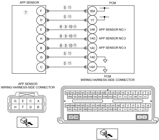
INSPECT REFERENCE VOLTAGE TO APP SENSOR
• Turn the ignition switch off.
• Disconnect the APP sensor connector.
• Turn the ignition switch to the ON position (Engine off).
• Measure the voltage between the APP sensor connector D or F terminal (wiring harness side) and the APP sensor connector C or G terminal (wiring harness side)
• Is the voltage between 4—6 V?
|
Yes
|
Go to the next step.
|
|
No
|
Repair if necessary.Then go to Step 12.
|
|
6
|
INSPECT FUNCTIONALITY OF APP CIRCUITS
-
Note
-
• Use the voltage measurements from Step 4.
• Are APP1, APP2 or APP3 out of range?
|
Yes
|
Go to the next Step.
|
|
No
|
Go to Step 11.
|
|
7
|
INSPECT FUNCTIONALITY OF APP SENSOR
• Turn the ignition switch off.
• Disconnect the APP sensor connector.
• Measure the resistance between the following APP sensor terminals (APP sensor component side).
-
― E and D or F: 600—1,370 ohms
― E and C or G: 720—1,660 ohms
― E and H: 1,300—2,960 ohms
― E and B: 1,250—2,860 ohms
― H and D or F: 750—1,720 ohms
― H and C or G: 660—1,520 ohms
― H and B: 1,230—2,810 ohms
― B and D or F: 710—1,640 ohms
― B and C or G: 580—1,340 ohms
― D or F and C or G: 200—470 ohms
• Are all the resistances within specifications?
|
Yes
|
Go to next Step.
|
|
No
|
Replace the accelerator pedal. Then go to Step 12.
|
|
8
|
INSPECT APP SENSOR SIGNAL CIRCUIT FOR OPEN CIRCUIT
• Disconnect the PCM connector.
• Inspect for continuity between the following terminals:
-
― P2121: APP sensor terminal E and PCM terminal 1AK
― P2126: APP sensor terminal H and PCM terminal 1AG
― P2131: APP sensor terminal B and PCM terminal 1AC
• Are there continuity?
|
Yes
|
Go to the next step.
|
|
No
|
Repair or replace suspected part, then go to Step 12.
|
|
9
|
INSPECT APP SENSOR SIGNAL CIRCUIT FOR SHORT TO GROUND
• Turn the ignition switch off.
• Inspect for continuity between the following terminals:
-
― P2121: APP sensor terminal E and body ground
― P2126: APP sensor terminal H and body ground
― P2131: APP sensor terminal B and body ground
• Are there continuity?
|
Yes
|
Repair or replace suspected part, then go to Step 12.
|
|
No
|
Go to the next Step.
|
|
10
|
INSPECT APP SENSOR SIGNAL CIRCUIT FOR SHORT TO POWER SUPPLY
• Turn the ignition switch to the ON position (Engine off).
• Measure the voltage between the following terminals:
-
― P2121: APP sensor terminal E and body ground
― P2126: APP sensor terminal H and body ground
― P2131: APP sensor terminal B and body ground
• Are the voltage B+?
|
Yes
|
Repair or replace suspected part, then go to Step 12.
|
|
No
|
Go to the next Step.
|
|
11
|
INSPECT APP SENSOR SIGNAL CIRCUIT FOR SHORT EACH OTHER
• Turn the ignition switch off.
• Disconnect PCM connector.
• Disconnect APP sensor connector.
• Measure the resistance between the following APP sensor terminals (wiring harness-side)
-
― P2121 E and H
E and B
E and D or F
E and C or G
-
― P2126 H and E
H and B
H and D or F
H and C or G
-
― P2131 B and E
B and H
B and D or F
B and C or G
• Are there resistance greater than 10 kilohms?
|
Yes
|
Go to the next step.
|
|
No
|
Repair or replace suspected part, then go to the next step.
|
|
12
|
VERIFY TROUBLESHOOTING OF DTC P2121, P2126 or P2131 HAS BEEN COMPLETED
• Verify that all disconnected connectors reconnected.
• Clear the DTC from the PCM memory using the M-MDS.
• Perform the KOEO or KOER self-test using the M‐MDS.
• Is the PENDING CODE for the DTC present?
|
Yes
|
Replace the PCM, then go to the next step.
|
|
No
|
Go to the next step.
|
|
13
|
VERIFY AFTER REPAIR PROCEDURE
• Perform “AFTER REPAIR PROCEDURE”.
• Are any DTCs present?
|
Yes
|
Go to the applicable DTC inspection.
|
|
No
|
Troubleshooting completed.
|