 |
ac9uuw00000266
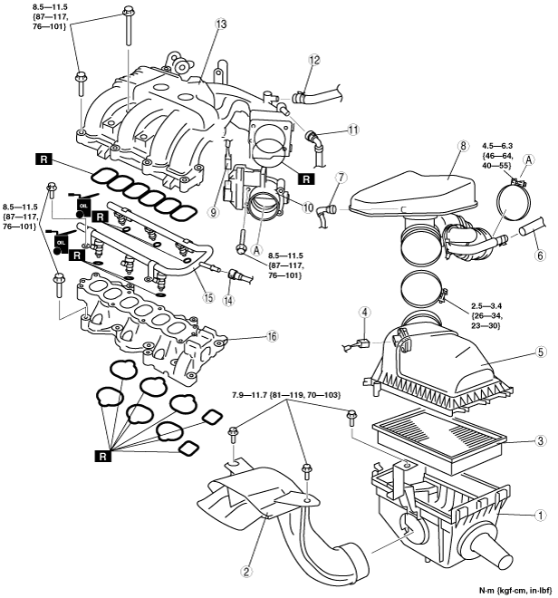
INTAKE-AIR SYSTEM REMOVAL/INSTALLATION [MZI-3.7]
id0113c3801900
1. Complete the “BEFORE SERVICE PRECAUTION”. (See BEFORE SERVICE PRECAUTION [MZI-3.7].)
2. Remove the battery. (See BATTERY REMOVAL/INSTALLATION [MZI-3.7].)
3. Remove the engine cover. (See ENGINE COVER REMOVAL/INSTALLATION [MZI-3.7].)
4. Remove in the order indicated in the table.
5. Install in the reverse order of removal.
6. Complete the “AFTER SERVICE PRECAUTION”. (See AFTER SERVICE PRECAUTION [MZI-3.7].)
ac9uuw00000266
|
|
1
|
Air cleaner case
|
|
2
|
Fresh-air duct
|
|
3
|
Air cleaner element
|
|
4
|
MAF/IAT sensor connector
|
|
5
|
Air cleaner cover
|
|
6
|
Vacuum hose (to power brake unit)
|
|
7
|
Ventilation hose
|
|
8
|
Resonance chamber
|
|
9
|
TP sensor connector
|
|
10
|
Throttle body
|
|
11
|
Vacuum hose (to purge solenoid valve)
|
|
12
|
Vacuum hose (to power brake unit)
|
|
13
|
Dynamic chamber
|
|
14
|
Fuel hose
|
|
15
|
Fuel distributor
|
|
16
|
Intake manifold
(See Intake Manifold Removal Note.)
|
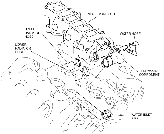
Intake Manifold Removal Note
1. Drain the engine coolant. (See ENGINE COOLANT REPLACEMENT [MZI-3.7].)
2. Disconnect the upper radiator hose.
ac9uuw00002457
|
3. Disconnect the lower radiator hose.
4. Disconnect the two water hose from the thermostat component.
5. Disconnect the thermostat component side of the water inlet pipe which is under the intake manifold.
6. Remove the intake manifold and thermostat component as a single unit.
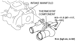
7. Remove the thermostat component from the intake manifold.
ac9wzw00000191
|
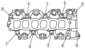
Intake Manifold Installation Note
1. Tighten the intake manifold installation bolts in the order shown.
ac9wzw00000245
|
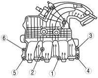
Dynamic Chamber Installation Note
1. Tighten the dynamic chamber installation bolts in the order shown.
ac9wzw00000246
|