|
1
|
VERIFY FREEZE FRAME DATA HAS BEEN RECORDED
• Has FREEZE FRAME DATA been recorded?
|
Yes
|
Go to the next step.
|
|
No
|
Record FREEZE FRAME DATA on the repair order, then go to the next step.
|
|
2
|
VERIFY RELATED SERVICE INFORMATION AVAILABILITY
• Verify related Service Information availability.
• Is any related Service Information available?
|
Yes
|
Perform repair or diagnosis according to the available Service Information.
• If the vehicle is not repaired, go to the next step.
|
|
No
|
Go to the next step.
|
|
3
|
VERIFY THE BRAKE PEDAL WAS APPLIED
• Was the brake pedal applied and released during the KOEO self-test?
|
Yes
|
Go to the next step.
|
|
No
|
Perform the KOER self-test.
Apply and release the brake pedal during the KOER self-test, then go to Step 10
|
|
4
|
INSPECT THE OPERATION OF THE BLAKE/TAILLIGHT
• Turn the ignition switch to the ON position (Engine off).
• Depress and release the brake pedal and check the blake/taillight operation.
• Do the blake/taillight operate correctly?
|
Yes
|
Go to the next step.
|
|
No
|
Repair or replace harness or blake/taillight, then go to Step 10.
|
|
5
|
INSPECT THE CRUISE CONTROL OPERATION
• Check for cruise control operation.
• Does the cruise control operate correctly?
|
Yes
|
Go to the next step.
|
|
No
|
Repair or replace suspected part, then go to Step 10.
|
|
6
|
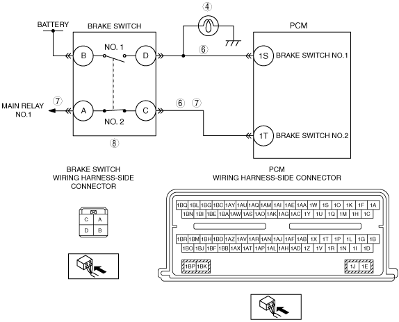
INSPECT BRAKE SWITCH AND PCM CONNECTOR FOR POOR CONNECTION
• Turn the ignition switch off.
• Disconnect the brake switch connector.
• Inspect for poor connection (such as damaged/ pulled-out pins, corrosion).
• Are there any malfunction?
|
Yes
|
Repair or replace suspected part, then go to Step 10.
|
|
No
|
Go to the next step.
|
|
7
|
INSPECT BRAKE SWITCH NO.1 CIRCUIT MALFUNCTION
• Turn the ignition switch to the ON position (Engine off).
• Measure the voltage between PCM terminal 1T (wiring harness-side) and body ground.
• Verify the following values when the brake pedal to the floor and releasing.
-
― Brake pedal fully depressed: more than 10 V
― Brake pedal fully released: less than 1.0 V
• Is the voltage normal?
|
Yes
|
Go to the next step.
|
|
No
|
Repair or replace suspected part, then go to Step 10.
|
|
8
|
INSPECT BRAKE SWITCH
• Inspect the brake switch.
• Is there any malfunction?
|
Yes
|
Repair or replace suspected part, then go to Step 10.
|
|
No
|
Go to the next step.
|
|
9
|
INSPECT FOR CORRECT PCM OPERATION
• Disconnect all the PCM connectors.
• Visually inspect for:
-
― Pushed out pins
― Corrosion
• Connect all the PCM connectors and verify that they seat correctly.
• Retrieve DTCs using the M-MDS.
• Is the PENDING CODE for this DTC present?
|
Yes
|
Go to the next step.
|
|
No
|
The system is correctly. Go to the next step.
|
|
10
|
VERIFY TROUBLESHOOTING OF DTC P1703:00 HAS BEEN COMPLETED
• Verify that all disconnected connectors reconnected.
• Clear DTC from memory using M-MDS.
• Perform the KOEO or KOER self-test.
• Is PENDING CODE same as DTC present?
|
Yes
|
Repeat the inspection from Step 1.
• If the malfunction recurs, replace the PCM.
Go to the next step.
|
|
No
|
Go to the next step.
|
|
11
|
VERIFY AFTER REPAIR PROCEDURE
• Perform the “AFTER REPAIR PROCEDURE”.
• Are any DTCs present?
|
Yes
|
Go to the applicable DTC inspection.
|
|
No
|
Troubleshooting completed.
|