|
1
|
VERIFY FREEZE FRAME DATA HAS BEEN RECORDED
• Has FREEZE FRAME DATA been recorded?
|
Yes
|
Go to the next step.
|
|
No
|
Record FREEZE FRAME DATA on the repair order, then go to the next step.
|
|
2
|
VERIFY RELATED SERVICE INFORMATION AVAILABILITY
• Verify related Service Information availability.
• Is any related Service Information available?
|
Yes
|
Perform repair or diagnosis according to the available Service Information.
• If the vehicle is not repaired, go to the next step.
|
|
No
|
Go to the next step.
|
|
3
|
VERIFY RELATED PENDING CODE OR STORED DTCs
• Turn the ignition switch off, then to the ON (Engine off).
• Verify related PENDING CODE or stored DTCs.
• Is the DTC P0685:00 present?
|
Yes
|
Go to the appropriate DTC troubleshooting procedures.
|
|
No
|
Go to the next step.
|
|
4
|
VERIFY WHETHER MALFUNCTION IS IN FUEL PUMP RELAY CONTROL CIRCUIT OR ELSEWHERE
• Turn the ignition switch off, then to the ON (Engine off).
• Verify related PENDING CODE or stored DTCs.
• Are DTCs P0230:00, P0231:00, or P0232:00 present?
|
Yes
|
Go to the next step.
|
|
No
|
Go to Step 14.
|
|
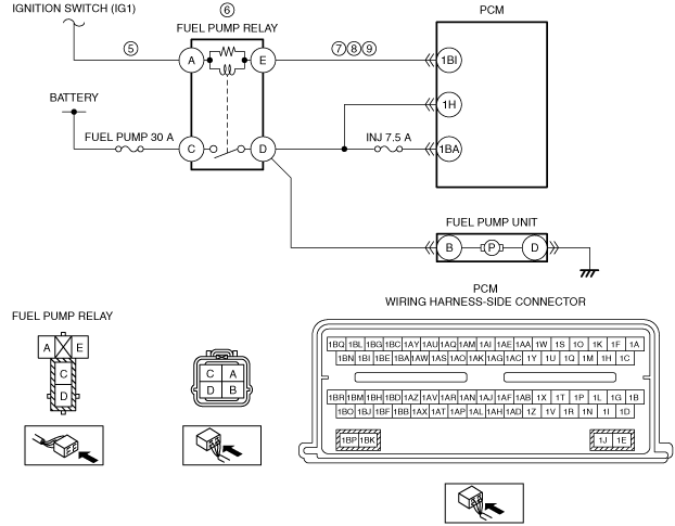
5
|
CHECK VPWR VOLTAGE TO FUEL PUMP RELAY
• Turn the ignition switch to the ON position (engine off).
• Measure the voltage between fuel pump relay terminal A (wiring harness-side) and body ground.
• Is the voltage greater than 10 V?
|
Yes
|
Go to the next step.
|
|
No
|
Repair for open circuit, then go to Step 15.
|
|
6
|
CHECK THE FUEL PUMP RELAY
• Inspect the fuel pump relay.
• Is the fuel pump relay normal?
|
Yes
|
Go to the next step.
|
|
No
|
Replace the fuel pump relay, then go to Step 15.
|
|
7
|
CHECK FUEL PUMP CONTROL CIRCUIT FOR SHORT TO POWER SUPPLY IN HARNESS
• Fuel pump relay is removed.
• Turn the ignition switch off.
• Disconnect the PCM connector.
• Turn the ignition switch to the ON position (engine off).
• Measure the voltage between PCM terminal 1BI (wiring harness-side) and body ground.
• Is the voltage less than 1 V?
|
Yes
|
Go to the next step.
|
|
No
|
Repair for short circuit, then go to Step 15.
|
|
8
|
CHECK FUEL PUMP CONTROL CIRCUIT FOR SHORT TO GROUND IN HARNESS
• Fuel pump relay is removed.
• PCM connector is disconnected.
• Turn the ignition switch off.
• Measure the resistance between PCM terminal 1BI (wiring harness-side) and body ground.
• Is the resistance greater than 10 kilohms?
|
Yes
|
Go to the next step.
|
|
No
|
Repair for short circuit, then go to Step 15.
|
|
9
|
CHECK FUEL PUMP CONTROL CIRCUIT FOR OPEN IN HARNESS
• Fuel pump relay is removed.
• PCM connector is disconnected.
• Measure the resistance between PCM terminal 1BI (wiring harness-side) and fuel pump relay terminal E (wiring harness-side).
• Is the resistance less than 5 ohm?
|
Yes
|
Go to the next step.
|
|
No
|
Repair for open circuit, then go to Step 15.
|
|
10
|
CHECK FOR FUEL PUMP RELAY CIRCUIT PROBLEM ALSO PRESENT
• Perform the KOER self-test.
• Are DTCs P0231:00 or P0232:00 present?
|
Yes
|
Go to the next step.
|
|
No
|
Go to Step 15.
(The system is operating normal at this time. The concern may have been caused by a loose or corroded connector.)
|
|
11
|
CHECK FP PRIMARY CIRCUIT INSIDE PCM
• Fuel pump relay is removed.
• PCM connector is disconnected.
• Turn the ignition switch off.
• Reconnect all disconnected connectors.
• Reinstall the fuel pump relay.
• Turn the ignition switch to the ON position (engine off).
• Access the PCM and monitor the FP PID.
• Is the PID state properly?
|
Yes
|
Go to Step 15.
(The system is operating normal at this time. The concern may have been caused by a loose or corroded connector.)
|
|
No
|
Go to the next step.
|
|
12
|
CHECK FUEL PUMP PRIMARY CIRCUIT INSIDE PCM WHILE CRANKING ENGINE
• Access the PCM and monitor the FP PID.
• While observing the PID, crank the engine.
• Does the PID display indicate a concern during crank?
|
Yes
|
Go to Step 15.
(The system is operating normal at this time. The concern may have been caused by a loose or corroded connector.)
|
|
No
|
The fuel pump primary circuit is normal in the harness and PCM.
Go to the next step.
|
|
13
|
VERIFY FUEL PUMP RELAY SECONDARY CIRCUIT LOW CONCERN ALSO PRESENT
• Perform the KOEO self-test.
• Is DTC P0231:00 present?
|
Yes
|
Go to the appropriate DTC troubleshooting procedures.
|
|
No
|
Go to Step 15.
(The system is operating normal at this time. The concern may have been caused by a loose or corroded connector.)
|
|
14
|
CHECK FUEL PUMP RELAY PRIMARY CIRCUITS
-
Note
-
• The PID indicates YES when a concern is present.
• Turn the ignition switch to the ON (engine off).
• Wait for 5 seconds.
• Access the PCM and monitor the FP PID.
• Observe the FP PID for an indication of a concern while carrying out the following:
-
― Shake, wiggle, and bend the FP circuit between the PCM and the FP relay
― Shake, wiggle, and bend the VPWR circuit between the electronic engine control power relay and the FP relay
― Lightly tap on the FP relay to simulate road shock
• Turn the ignition switch off.
• Visually inspect the PCM connector and wires as far back as the main loom for damage.
• Visually inspect the fuel pump relay connector and wires as far back as the main loom for damage.
• Is a concern present?
|
Yes
|
Isolate the concern and repair if necessary.
Go to the next step.
|
|
No
|
Go to the next step.
(The system is operating normal at this time. The concern may have been caused by a loose or corroded connector.)
|
|
15
|
VERIFY TROUBLESHOOTING OF DTC P0230:00 HAS BEEN COMPLETED
• Verify that all disconnected connectors are reconnected.
• Clear the DTC from the PCM memory using the M-MDS.
• Perform the KOEO or KOER self-test.
• Is the same DTC present?
|
Yes
|
Repeat the inspection from Step 1.
• If the malfunction recurs, replace the PCM.
Go to the next step.
|
|
No
|
Go to the next step.
|
|
16
|
VERIFY AFTER REPAIR PROCEDURE
• Perform the “AFTER REPAIR PROCEDURE”.
• Are any DTCs present?
|
Yes
|
Go to the applicable DTC inspection.
|
|
No
|
Troubleshooting completed.
|