|
1
|
VERIFY FREEZE FRAME DATA HAS BEEN RECORDED
• Has FREEZE FRAME DATA been recorded?
|
Yes
|
Go to the next step.
|
|
No
|
Record FREEZE FRAME DATA on the repair order, then go to the next step.
|
|
2
|
VERIFY RELATED SERVICE INFORMATION AVAILABILITY
• Verify related Service Information availability.
• Is any related Service Information available?
|
Yes
|
Perform repair or diagnosis according to the available Service Information.
• If the vehicle is not repaired, go to the next step.
|
|
No
|
Go to the next step.
|
|
3
|
VISUALLY INSPECT HO2S HARNESS
• Turn the ignition switch off.
• Disconnect the suspect HO2S connector.
• Visually inspect suspect HO2S for:
-
― Pinched, shorted, and corroded wiring and pins
― Oil or water contamination
― Crossed sensor wires
― Damaged HO2S
• Is a concern present?
|
Yes
|
Repair or replace the malfunctioning part according to the inspection results, then go to Step 11.
|
|
No
|
Go to the next step.
|
|
4
|
CHECK FOR UNMETERED AIR LEAKS
-
Note
-
• Fuel calculations can be affected by unmetered air leaks.
• Carefully inspect the following areas for potential air leaks:
-
― Hoses connecting to the MAF sensor assembly
― Hoses connecting to the throttle body
― Intake manifold gasket leaks
― PCV system
― Vacuum lines are disconnected
― Improperly seated engine oil dipstick, tube or oil fill cap
• Is a concern present?
|
Yes
|
Repair the source of the air leak.
Go to Step 11.
|
|
No
|
Go to the next step.
|
|
5
|
INSPECT FOR SOURCE OF POTENTIAL HO2S CONTAMINATION
• Investigate the following items as potential sources of HO2S contamination:
-
― Use of unapproved silicon sealers
― Fuel contaminated by silicon additives
― Excessive oil consumption
― Glycol leaking internally in the engine
― Lead-contaminated fuel
― Short drive cycles in cold weather
― Use of unapproved cleaning agents
• Is a concern present?
|
Yes
|
Repair the source of the contamination.
Change the engine oil and oil filter.
Go to Step 11.
|
|
No
|
Go to the next step.
|
|
6
|
INSPECT EXHAUST SYSTEM AND FUEL SELECTION CONCERNS
• Inspect the suspect exhaust system for the following:
-
― Leaks, cracks, or punctures at flanges and gaskets
― Aftermarket accessories and performance modifications
― Exhaust leaks at the HO2S
• Verify with the customer that flex fuel is not being used on a non-flex fuel vehicle.
• Is a concern present?
|
Yes
|
Repair or replace the malfunctioning part according to the inspection results, then go to Step 11.
|
|
No
|
Go to the next step.
|
|
7
|
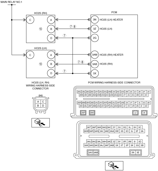
CHECK HO2S CIRCUIT(S) FOR OPEN IN HARNESS
-
Note
-
• Diagnose the suspect sensor indicated by the DTC.
• Verify the harness pins are in the correct location.
• Suspect HO2S connector is disconnected.
• Turn the ignition switch off.
• Disconnect the PCM connector.
• Check the connector (both halves) for any water contamination and replace if necessary.
• Measure the resistance between the following terminals (wiring harness-side):
-
― P2A01:00:
-
• HO2S (RH) terminal B—PCM terminal 3Z
• HO2S (RH) terminal D—PCM terminal 2G
― P2A04:00:
-
• HO2S (LH) terminal B—PCM terminal 3AB
• HO2S (LH) terminal D—PCM terminal 2G
• Is the resistance less than 5 ohm?
|
Yes
|
Go to the next step.
|
|
No
|
Repair for open circuit, then go to Step 11.
|
|
8
|
CHECK HO2S CIRCUIT FOR SHORT TO GROUND
• Suspect HO2S and PCM connectors are disconnected.
• Measure the resistance between the following suspect HO2S terminals:
-
― P2A01:00:
-
• HO2S (RH) terminals B and D (wiring harness-side)
• HO2S (RH) terminal B (wiring harness-side) and body ground
― P2A04:00:
-
• HO2S (LH) terminals B and D (wiring harness-side)
• HO2S (LH) terminal B (wiring harness-side) and body ground
• Is the resistance greater than 10 kilohms?
|
Yes
|
Go to the next step.
|
|
No
|
Repair for short circuit, then go to Step 11.
|
|
9
|
CHECK HO2S CIRCUIT FOR SHORT TO VOLTAGE
• Suspect HO2S and PCM connectors are disconnected.
• Turn the ignition switch to the ON position (engine off).
• Measure the voltage between the following suspect HO2S terminals (wiring harness-side) and body ground:
-
― HO2S (RH) terminal B (P2A01:00)
― HO2S (LH) terminal B (P2A04:00)
• Is there any voltage?
|
Yes
|
Repair for short circuit, then go to Step 11.
|
|
No
|
Go to the next step.
|
|
10
|
CHECK HO2S CIRCUIT CONTINUITY
-
Note
-
• HO2S is displayed as O2S on the scan tool.
• Suspect HO2S and PCM connectors are disconnected.
• Turn the ignition switch off.
• Reconnect the PCM connector.
• Connect a 5 A fused jumper wire between suspect HO2S terminals (wiring harness-side) B and D
• Start the engine and run it at idle.
• Access the PCM and monitor the suspect HO2S signal PID.
-
― O2S11 (VOLT) PID (P2A01:00)
― O2S21 (VOLT) PID (P2A04:00)
• Is the voltage greater than 1 V?
|
Yes
|
Replace the HO2S, then go to the next step.
|
|
No
|
Go to the next step.
(The system is operating normal at this time. The concern may have been caused by a loose or corroded connector.)
|
|
11
|
VERIFY TROUBLESHOOTING OF DTC P2A01:00, P2A04:00 HAS BEEN COMPLETED
• Verify that all disconnected connectors are reconnected.
• Clear the DTC from the PCM memory using the M-MDS.
• Perform the KOEO or KOER self-test.
• Is the PENDING CODE for this DTC present?
|
Yes
|
Repeat the inspection from Step 1.
• If the malfunction recurs, replace the PCM.
Go to the next step.
|
|
No
|
Go to the next step.
|
|
12
|
VERIFY AFTER REPAIR PROCEDURE
• Perform the “AFTER REPAIR PROCEDURE”.
• Are any DTCs present?
|
Yes
|
Go to the applicable DTC inspection.
|
|
No
|
Troubleshooting completed.
|